This thread has been locked.

If you have a related question, please click the "Ask a related question" button in the top right corner. The newly created question will be automatically linked to this question.

TPS61088: why TPS61088RHL driver makes a lot of noise?

Part Number: TPS61088

Hello, 

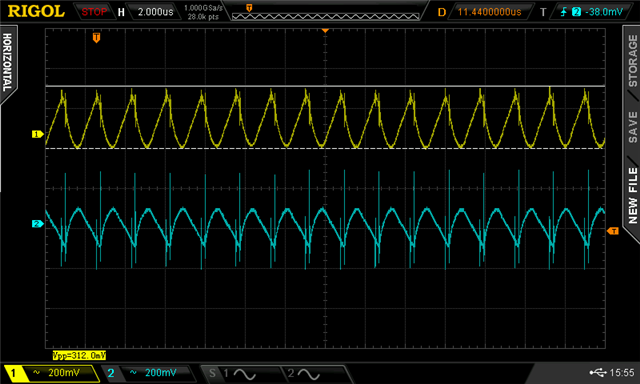
I have been working with one of our projects which require 12 V power supply with at least 1.5 A current. I used webench power designer tool to create simple 5 V-10 V input and 12 V 2 A output design. Since input voltage is controlled, we can provide from 5 to 12 V, but since 12 V to 12 V boost converter is not very practical, I searched for design that is in 5 - 10 V. I used this one : ://webench.ti.com/appinfo/webench/scripts/SDP.cgi?ID=AA10D686D6FEB9D1 . Manufactured PCB design and assembled whole device with proper components. But the problem is that the output is very noisy. At most, our system consumes around 700 mA, so I tested this scenario with 17 ohm power resistor directly connected to this converter output. I measured input and output voltage with osciloscope, I also used lab bench power supply with 10 V 2.2 A output. Yellow signal is the input and Blue signal is the output of TPS61088 converter. Why it gets so noisy ? load doesn't consume 1 A. It even effects the input, how can I solve this problem ? 

  • Hi Dominukas,

    thank you for reaching out.

    The output is fluctuating and below are some possible reasons:

    1. the input voltage is not stable.

    This input supply must be well regulated. If the input supply is located more than a few inches from the converter, additional bulk capacitance may be required in addition to the ceramic bypass capacitors. A typical choice is an electrolytic or tantalum capacitor with a value of 47 μF.

    Also, the input wires but be taken care. if the wire is too thin and long, the resistance will be large. 

    2. the loop is not stable.

    The parameter in the webench is effective value.

    High-capacitance ceramic capacitors have a DC bias effect, which has a strong influence on the final effective capacitance. The differences between the rated capacitor value and the effective capacitance result from package size and voltage rating in combination with material. A 10-V rated 0805 capacitor with 10 μF can have an effective capacitance of less 5 μF at an output voltage of 5 V.

    3. other reasons.

    Other reasons include Inappropriate parameters by mistake and so on.

    Please tell me if you have more findings or questions.

    Best Regards,

    Fergus

  • I don't think that the problem is with input voltage, because we used lab bench power supply with constant voltage. Wires could be the problem, because for tests we used >30 cm length cables that are not too thick, but we also tried adding 47 uF electrolytic capacitor at the input, which showed no results. Our loop capacitors all have 16 V rating, we use 10 V at the input, so this maybe the problem, we should switch them for higher rating to test that. 

  • Hi Dominykas,

    please feel free to connect me if you have more findings.

    Best Regards,

    Fergus