This thread has been locked.

If you have a related question, please click the "Ask a related question" button in the top right corner. The newly created question will be automatically linked to this question.

LMR38010: holding output when pulled up with negative current

Part Number: LMR38010
Other Parts Discussed in Thread: TPS40055

Hi,

I have a question concerning the FPWM of the LMR38010FSDDAR.

Take a basic circuit with 48V input and 9V output.

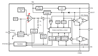
In my application it might be that the output is pulled higher than 9V. I thought FPWM would then pass a negative current through the low side FET to maintain the 9V output.

As this does not happen, my question is if I am thinking of it wrong? Or maybe the circuit is wrong? Or Digikey did not supply the F part?

Any help is welcome, thanks in advance!

Regards,

Bert

  • Hi Bert,

    FPWM is added so that the switching converter maintains the same switching frequency at light load, which helps with transient response and lower output voltage ripple at light load conditions. If the output voltage is raised higher than expected, we should expect the device to stop switching until the device senses that the output voltage is below regulation target, at which point it will begin switching again.

    Do you have any waveforms to show what you are seeing? 

    Thanks,

    Richard  

  • Hi Richard,

    yes, that is what I am getting. But as stated in the manual (p15, 8.3.8) the inductor current should be allowed to go negative. So it should stay in regulation and try to sink the current to gnd via low side fets. On p5 7.5 you also find this negative current to be valid only for the FPWM version.

    Am I getting this wrong? So now two quadrant (QI/QIV) supply with FPWM?

  • Hi Bert,

    The negative current limit is what the inductor current is allowed to drop down to if conducting negative current (i.e. at 0A, but if your ripple current is 1.2Apk-pk, the negative current limit will cap the current at -0.5A. But that is different than having the output voltage being forced higher than the regulation target. 

    In the block diagram, if the FB is simply higher than the reference voltage, COMP will not issue a pulse.

    Thanks,

    Richard

  • Yes, I see...thanks Richard!

    So, is there any TI switching regulator for 2 or 4 quadrant use?

    Thannks and regards,

    Bert

  • Hi Bert,

    I think for your case, you might be suited with a zener diode at the output to clamp it in cases where the output rises above the regulation target. 

    With regards for 2 or four quadrant switching regulators, you can implement it with some devices, but it seems like a high-complexity design. I've attached an app note here: https://www.ti.com/lit/an/slua060/slua060.pdf?ts=1716314386363&ref_url=https%253A%252F%252Fwww.google.com%252F

    Thanks,

    Richard 

  • Hi Richard,

    as I have user dependent output voltage a zener is no choice, it would dissipate too much while constantly in this mode.

    But I found the TPS40055 to have "two-quadrant" source/sink mode (p8), do you know how this device behaves when Vo is higher than programmed? Will it act as a current source while still regulating the output voltage?

  • Hi Bert,

    I see. I'm not too familiar with this device so you will have to submit another thread to the engineers who support the TPS40055 device who can point you in the right direction. 

    Thanks,

    Richard