This thread has been locked.

If you have a related question, please click the "Ask a related question" button in the top right corner. The newly created question will be automatically linked to this question.

TLV711: TLV7111533DDSER

Part Number: TLV711

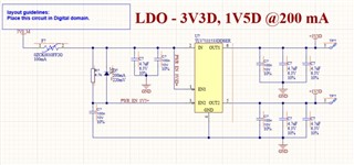
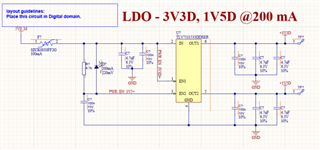
Hi, I am trying to find out/confirm the timing relationship between EN1, 2 and VOUT1, VOUT2.

I have a power sequencing requirement and can't have VOUT2 (1.5V) reaching its final value before VOUT1 (3V3) reaching its final value. But they can reach the final value at the same time.

I can see Startup time tSRT is a common value for this device. Can you please advise if I can connect the EN1, 2 pin to VIN direct? Or should I do some RC network to delay EN2?

Thanks.

Regards

Billy

  • Hi Billy,

    Can you use a voltage divider on VOUT1 to EN2 such that EN2 threshold does not trip until VOUT1 reaches a certain threshold?  Let's say you trip the EN2 threshold when Vout1 reaches 80% of steady state (to account for tolerances).  Then I would think your requirement that Vout1 reaches steady state at or before Vout2 would be met.

    Thanks,

    Stephen

  • Hi Stephen, Thanks for this reply.

    I have done the circuit below. My assumption was the 3V3D will be 98% * 3.3V in 100 us. The R-C provide a delay of 100us for the EN2 to reach 0.9V (VEN(TH_MAX.). This will make the VOUT2 (1V5) to reach its 98% 200 us after the device see the VIN.

    Do you think my thought process is correct? I was assuming that the enable pin current is about 25uA and the 4.7kR will limit the current to about 30x of it.

    I am not so keen on potential divider.... fearing of current consumption.

    I may be wrong in this assumption. Please advise.

    Thanks

    Regards

    Billy

  • Hi Billy,

    This is another method that might work.  Keep in mind that it can be harder to predict the turn on time for this approach as it depends on the RC time constant, and the capacitor tolerance is usually an order of magnitude larger than a resistor tolerance.  Also consider that the enable turn on / off thresholds do not consider the "grey zone" regions in between the thresholds.  Thus, your LDO2 may turn on before you predict and you'll need to increase the RC time constant to guarantee it will always turn on late enough to meet your requirement. 

    Perhaps you should place the RC time constant circuit on Vout1 instead of Vin?  Then EN2 is more a function of VOUT1 than Vin, which gets you closer to the type of control you are looking for.

    Thanks,
    Stephen