This thread has been locked.

If you have a related question, please click the "Ask a related question" button in the top right corner. The newly created question will be automatically linked to this question.

LM5168PEVM: LM5169

Part Number: LM5168PEVM
Other Parts Discussed in Thread: LM5169, , LM5168

Tool/software:

Hi ,


I want to use LM5169 in my application, the application is an exact match to what I am looking for, 6V - 120V input, 5V, 0.6A max Load.

To try it our I ordered the LM5168PEVM eval board and ordered LM5169PDDAR  separate units. I used the components value calculator available of the this part TI webpage. COT Type 3 , mode of operation and 100KHz switching frequency.

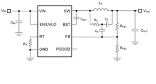
I replaced the original components on the eval board with  below components 

RT= 124kohm, 0.1W 1%

L0 = 150uH, 1.2 A Saturation current

Cin = 2 x 2uF 200V caps

Cout = 33uF, 20V

Ra = 442kohm, 0.1 W, 1%

Rfb2 = 143Kohm


The out voltage I see is 5.3V, with the load connected the value stays or is reduced a little , which is fine for me. But as soon as I take off the load the output slowly goes down to 0V and the output never comes up after reconnecting the load. I assume it goes to shutdown without load, but I dont see any such description in the datasheet.

However if I use the original LM5168PEVM eval board as is by replacing the Rfb2 =143Kohm resistor ( just to test with a 0.25A load, as LM5168 only supports 0.3A max). I dont see the same shutdown behavior.

Please help.

Regards

Abhi

  • Hello Abhi,

    I suspect the boot to switch voltage is causing Vboot supply to go into UVLO.

    Can you redesign your LM5169 with 56uH inductor (ripple injection etc) and retry.  Thanks.

    David.

  • Hello David,

    There was one error in my first post the Ra should have been 452kohm and not 442 Kohm, any ways this did not give me success either.

    With no luck,  I built my own board on dotted PCB. Here at least I see stable 5.04V @ open load , but gets unstable as I increase the Vin beyond 15V. Going back to 12V Vin, where the Vout is stable 5.04 I connect my load and as soon as I connect my load the Vout drops to 4.3V with 1mA drawn at the load . Now as I increase the Vin to 50V no change at the out voltage but at around 50V Vin the IC burns up.

    I built another board but same results. I tried 56uH and 100uH inductors but no luck. 

    The buck is not able to provide current to the load and the Vout drops. Not sure why is that so.

    Thanks

    Abhi

  • Hello Abhi,

    Suggest using the online design calculator filling in your specification and checking your design against it.  If there are no discrepancies fill free to reopen thread.  Thanks.

    David.

  • I have using the excel tool available online, the other Webench Power designer does not give show up any LM5169 based reference designs.

    Another update, I tried increasing the switching frequency from 100KHz to 250KHz , by changing the Rt resistor to 49.9K , but no improvement.

    Upon loading I see the ringing waveform at the SW pin, check this video.

  • Hello Abhishek 

    [However if I use the original LM5168PEVM eval board as is by replacing the Rfb2 =143Kohm resistor ( just to test with a 0.25A load, as LM5168 only supports 0.3A max). I don't see the same shutdown behavior] ==> How about trying to replace the component one by one ? I think you can #1 change RFB2 , #2  populate LM5169 , #3 Change RT.....then I guess you can find what causing the issue easily. 

    -EL  

  • Hello,

     I think you responded to my original post, after which I have made changes and made my own board and I followed the same steps .

    If you see the ringing waveform I posted in my previous post, I dont understand what could be causing it. Upon researching I found these issues are solved by snubber circuits, but I dont see any recommendation in the datasheet. and I assume that the IC itself must be taking care of it. But not sure then why do I see it.

    Thanks

    Abhi 

  • Hello Abhishek 

    Good to hear that you were able to resolve the issue by adding a snubber. Usually the root cause is a noise injection between VIN-SW or SW-GND if the issue is solved by adding a snubber.  

    -EL 

  • Sorry, I did not mean to say that snubber resolved my issue. I meant that could be the soulution but I dont want to add extra components to my design. I dont see anywhere in the application notes where it states a need for the snubber. I believe this compensation is already taken care of inside of the LM5169. I am just trying to figure out why is it happening with my handmade proto boards.

    Thanks

    Abhi

  • Hello Abhishek 

    Usually, the switching noise can be minimized by reducing the switching loop area. Please check the 'Critical Current Loops in the Buck Converter' in the datasheet. 

    -EL