


Other Parts Discussed in Thread: LP5891
Tool/software:
I have two questions that I’d like to ask both of you:
- We are attempting to measure the PWM signal of the “LP5891” IC. To do so, we connected an oscilloscope to LINE0 and LINE1. CH1 represents the waveform of LINE0, and CH2 represents the waveform of LINE1. The oscilloscope display is as follows:
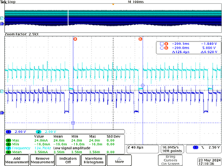
Could you please identify the type of signal represented by this waveform?
2.We are also trying to verify whether the current flowing through a single LED matches the specified current. Here’s the system diagram we used for measurement:
We measured a total input current of 705mA for TI’s LED panel.
The TI circuit design uses 16 scan lines, and there are a total of 768 LEDs.
Our calculation process is as follows: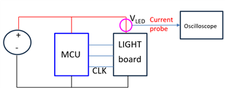
- Current per LED:
705/768mA=0.918mA
- Total current for 16 scan lines:
0.918mA×16=14.68mA
However, this value does not match the originally set maximum output current of 20mA per single channel.
It appears to be approximately 6mA lower.
Could you please review the register settings provided below?
