This thread has been locked.

If you have a related question, please click the "Ask a related question" button in the top right corner. The newly created question will be automatically linked to this question.

LM5109B: Drive current consultation

Part Number: LM5109B

Tool/software:

Hi team,

My customer want to use a LM5109B to drive three MOSFET at the same time. So I want to know how much general drive current of a general MOSFET and if we can use a single LM5109B to drive three MOSFET at the same time? Thanks.

BR,

Ryker

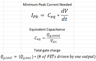
  • Could we use below equation to evaluate the drive current? 

  • Hi,

    Due to the holiday in the US on 27 May 2024, many of the device experts are currently out of the office. When they return, they will look into this and provide a response. Please expect some delay accordingly.

    Thanks,
    Pratik

  • Hey Ryker,

    Thank you for reaching out with your question regarding the LM5109B.

    Yes, the LM5109B is capable of driving three MOSFETs in parallel. The drive current requirements are dictated by the desired rise/fall time, total Qg of the FETs being driven, and desired Vgs. Take a look at the following FAQ that has an Excel file for calculating the drive current for your application. Note that the Max Gate Charged at desired Qg is the addition of all three MOSFETs Qg.

    [FAQ] LM2105: Half-Bridge Gate Driver Minimum Current Calculator

    The gate resistance will also change the rise and fall times of the turn-on/turn-off of the FETs.

    Let me know if you have any further questions.

    Thank you,

    William Moore

  • Hi William,

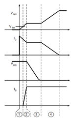
    Thanks for your reply. I have one more question. The rise time of MOSFET corresponds to the ③ process as below. So why use the Qg rather than (Qgs + Qgd) in equation? Thnaks. 

    Best Regards,

    Ryker

  • Hey Ryker,

    Qgs is the gate charge needed for the FET to reach the ON state. While Qds is the charge needed for after the ON state is reached until Vds begins to drop.

    The Qg is the total gate charge required for gate-source voltage to rise from 0 to 10V (or what it is rated/specified at). This could be simplified as Qg = Qgs + Qgd + Charge needed for Vgs to reach 10V. So, that is why when looking at gate drive and rise and fall times, you have to use Qg to determine what is needed for Vgs to rise completely.

    Let me know if you have any further questions.

    Thank you,

    William Moore

  • Hi William,

    The rise time of MOSFET is corresponding to Qg or (Qgs + Qgd)? I have check the Application Report as below, which indicates the rise/ fall time of MOSFET is '②+③' (Qgs + Qgd) as below (Vds drop to low voltage), but the time of Qg is '①+②+③+④'. So my concern is the 'dt' and 'Qg' don't correspond.

    Fundamentals of MOSFET and IGBT Gate Driver Circuits (Replaces SLUP169) (Rev. A) (ti.com)

    Best Regards,

    Ryker

  • Hey Ryker,

    Qg is needed to determine full rise time as it is the charge from the origin (0V) to when Vgs equals the drive voltage (~10V). This is for the full rising edge of the FET turn on.

    Qgs and Qgd are just intermediate portions of the total Qg as you mentioned, they are just for sections 2 and 3 of the above graph.

    For the correspondence of dt and Qg, dt is the total time it takes for Vgs to rise from 0V to drive voltage (~10V) and the total gate charge (Qg) is the gate charge of that entire transition from 0 to 10V.

    Let me know if you have further questions.

    Thank you,

    William Moore