


Tool/software:
Dear TI support team,
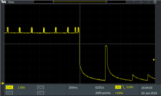
I am working on a design including the BQ51003 as a wireless QI receiver. It consists of the RX coil (760308101214 from Wuerth Elektronik), two ferrite sheets of 0.3mm thickness (354006 from Wuerth Elektronik), a PCB (see schematic attached) and a LIR2050 battery.
I meanwhile managed to stabilize this design in terms of the occasional interruptions that I observed earlier during my investigations: BQ51003: Waveform at FOD and ILIM pins - Power management forum - Power management - TI E2E support forums In particular I have added two circular ferrite sheets of 23mm diameter and 0.3mm thickness between the RX coil and the PCB to improve the shielding of the PCB. On top of that, I have replaced R6 in the schematic by a fixed 10kR resistor to disable the TS functionality since there are currently two resistors missing in the design in order for it to work as intended.
With these changes the battery is now reliably charging with 4 different Qi charging pads that I have available for testing. At the same time I am still struggling to establish a stable power transfer with two other transmitters (NORDMÄRKE from Ikea and 21310 from Trust). My assumption is that this a result of increased distance or worse coupling between the TX and RX coil for these two charging pads compared to the others.
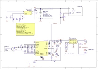
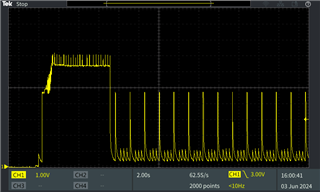
Please see below two waveforms of the RECT pin when I place the RX coil directly on the Ikea charging pad. At first it seems like the power transfer is successfully established for appr. 6 seconds before the RECT pin eventually drops low. The second screenshot is a zoom of the first screenshot when the RECT voltage drops low.
When I remove the housing of the Ikea charging pad and place the RX directly on top of the TX coil I end up with a stable power transfer without the voltage drop as seen above. Please see the picture below for a comparison of the coil dimensions.

I have already adapted the resonance circuitry for the additional ferrite sheets with the following values:
- LS measured as 28.11uH
- LS' measured as 31.18uH
- C1 calculated as 81.24nF --> 47nF + 33nF chosen for testing
- C2 calculated as 911.38pF --> 910pF chosen for testing
Apart from that I have also tried different values for the COMM capacitors (10nF, 22nF, 33nF) without any significant improvement.
Do you have any suggestions for changes to my design that could help me to overcome this problem?
I am very limited in terms of the available space inside the receiver housing, so choosing a larger coil is not really an option. Nevertheless, I could give another RX coil a try that I have available here. It's the 760308101303 from Wuerth Elektronik with 47uH and 26mm in diameter. Would that make sense to improve the coupling factor between the TX and RX?
Any kind of help is highly appreciated. Thank you in advance! 
Best regards
Leonhard
