This thread has been locked.

If you have a related question, please click the "Ask a related question" button in the top right corner. The newly created question will be automatically linked to this question.

TPS65916: TPS659162; What is the condition under which the "RESET_OUT" signal is at the Lo level?

Part Number: TPS65916
Other Parts Discussed in Thread: AM5716

Tool/software:

Hello, experts.

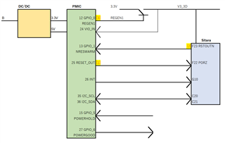
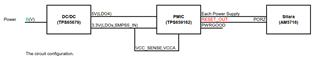
Our set has the following circuit configuration.

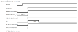
When "B" voltage is 13.2V, PMIC's "RESET_OUT" is High Level.

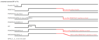
But "B" voltage is 7V, "RESET_OUT" is going to Lo level after 45 seconds form power on.
Then the output voltage levels of DC/DC(5V and 3.3V) are no probrem. 
The output of the PMIC is OK(Each voltage level is OK).
The "PWRGOOD"  remains at High level.(I thinki it is OK).

We would like to know why the "RESET_OUT" signal goes to Lo level.
Is it due to commands from the AM5716 (via I2C)?

  • Hi Atsushi,

    I'm looking into this and when I have more information or have some follow up questions I will be able to provide a more meaningful response, but need to dig deeper first.

    Thanks,
    Field

  • Hi Atsushi,

    • Is the RESET_OUT going low and staying low in your above scenario? Or does it eventually come back up?
    • What is the status of the POWERHOLD before, during, and after this process?
      • PWRON pin?
      • PWRDOWN pin?
      • SW_RST bit?
      • DEV_ON bit?
      • INT pin?
      • GPIOs?
    • Can you check to see if there are any interrupts pending?
    • Is there any issue with the output from the DC/DC TPS65679?
    • I'm unsure if the PORz can assert this low, but this could be a reason? But I am too unfamiliar with this AM5716 device to be able to provide more information regarding that.
    • A schematic may be helpful.

    I think the above information would be helpful in order to start narrowing this down.

    Thanks,
    Field

  • Hi Field-san,

    Thank you for your response.
    I will answer the following.
    This will be the scenario we want and the timing chart for NG.
    Each signal line is drawn in it.


    I will check SW_RST and DEV_ON are write it later.

    I don't think there is any other interrupt.
    DC/DC outputs (3.3 V and 5 V) are stable.
    The block diagram is shown below.


    Observing the waveform,
    [1]First, RESET_OUT goes to Lo level for Sitara.
    [2]Sitara then brings the RSTOUTN to the Lo level.
    [3]Finally, GPIO_0 (REG1EN) of PMIC goes to Lo level and cuts off power supply 3.3 V of Sitara.
    In this state, PMIC will not start even if POWERHOLD is set from Lo to Hi level.


    Thank you very much,
    Atsushi

  • Hi Atsushi,

    So GPIO_1 is not going low at all before RESET_OUT? It looks like there are similar issues when this was the case. RESET_OUT is driven low when there is a warm-reset, or if there is an off request. Which looks like POWERHOLD can drive this, does this remain high during the whole time while RESET_OUT is going low, before and after? My 2nd bullet point above are all from the 'off request' table, and is why I am asking about these. Knowing the status of these bits, or perhaps being able to change these may help. Because you don't see this problem when 'B' is a higher value I don't believe it is from some of these. Would you have a schematic that you can provide? As well as some oscilloscope captures of the above? 

    Is there any issue with the output from the DC/DC TPS65679?

    Thanks,
    Field

  • Hi Field-san,

    Thank you for your comment.
    The waveform by the oscilloscope is acquired again.
    Also check the register bits.

    Please wait a little longer.

    DC/DC output is normal.

    Thank you and best regards,

  • Hi Atsushi,

    Understood, please provide them at your convenience.

    Would you have a schematic that you can provide?

    Thanks,
    Field

  • Hi Field-san,

    I'm sorry for the delay.
    The waveform was observed with an oscilloscope.
    I will send you the circuit diagram (I can't make it public.) and waveform file by email. What should I do?

    Sorry, I haven't checked the register bits yet.

    Thank you and best regards,

  • Hi Atsushi,

    Can you send these via email to pyi@ti.com and f-tolson@ti.com

    Thanks,
    Field

  • Hi Field-san,

    Good day.

    The firmware agent is not available and has not yet checked the registers.

    I sent you the circuit diagram and waveform last week, but I got the waveform additionally, so I will expand it.

    Waveforms with I2C communication disabled(Left side) and enabled(Right side).

    We thought it would be confusing and didn't explain until now, but our system monitors Sitara's operation by FPGA (IC60).
    If the FPGA determines that the Sitata is not up, it resets the PMIC after 60 seconds (POWERHOLD signal) and waits another 60 seconds.
    If Sitara does not start in the meantime, power off PMIC.

    If I2C is disabled, Sitara does not start and is powered down by the FPGA after 120 seconds.
    If I2C is enabled, PMIC sets RESETOUT to Lo after 45 seconds. PMIC is not restored even if it is reset by POWERHOLD signal.
    Are these differences due to I2C commands (SW_RST bit? , DEV_ON bit?)?

    Thank you and best regards,

  • Hi Atsushi,

      Since it's a legacy device; I need more time to check in details and answer you later.

    Thanks!

    Phil

  • Hi Phil-san,

    Thank you for your reply.
    I look forward to hearing from you.

    Thank you and best regards,
    Atsushi

  • Hi Atsushi,

       I didn't get chance today; I'll try to check in details tomorrow and answer you then.

    Thanks!

    Phil

  • Hi Atsushi,

      Can you please capture the the output voltage levels of DC/DC(5V and 3.3V) by a scope during power up? They're inputs for the PMIC; I doubt there is a very narrow glitch to trigger a UVLO fault of the PMIC VCCA_SENSE pin and then the PMIC pulls its RESET_OUT (Maybe INT_OUT as well) low to let the MCU to handle the fault. 

    Thanks!

    Phil

  • Good day Phil-san,

    The waveform (5V,3.3V) of NG (Input voltage 7V) and OK (Input voltage 12V) were captured.
    In both cases, glitch occurred at 3.3V about 50ms after power on.
    However, the RESET_OUT and INT signals did not change at this time.
    In addition, no other glitches occurred.


    The waveform on the left is for NG and the waveform on the right is for OK.

    Thank you and best regards,
    Atsushi

  • Hi Atsushi-san,

      Can you please figure out the issue causing the glitch first? I think the "RESET_OUT" signal going Lo level issue should be fixed after the glitch issue fixed. 

    Thanks!

    Phil

  • Good day Phil-san,

    As you say, measures for glitch may be necessary.
    However, we consider it separately from the problem that the RESET_OUT signal becomes Lo level this time.

    The reasons are as follows:.
     *As you can see from the capture sent yesterday, even if normal voltage (12V) is applied, glitch still occurs, but the set starts(RESET_OUT does not become Lo).

     *The glitch occurs approximately 50 ms after 3.3V has risen. RESET_OUT, on the other hand, reaches the Lo level after 45 seconds.
    Even if it is detected by VCC_SENCE(also VCCA), it is unlikely that RESET_OUT will reach Lo level after 45 seconds.

     *If I2C communication between Sitara and PMIC is shunted (Remove I2C line pull-up resistor), RESET_OUT will not go to Lo level.

    This suggests that I2C controls RESET_OUT to the Lo level, which was not created by the software team.
    Therefore, I have the software team investigate the command exchange in I2C, but it is taking time.
    In addition, we have asked the software team to investigate the register contents(SW_RST and DEV_ON) that Field Toison-san requested.

    I think RESET_OUT is at Lo level by the I2C command. What do you think?


    Thank you and best regards,
    Atsushi

  • Hi Atsushi-san,

     Since " *If I2C communication between Sitara and PMIC is shunted (Remove I2C line pull-up resistor), RESET_OUT will not go to Lo level.'; I agree with you "RESET_OUT is at Lo level caused by the I2C command."

    Thanks!

    Phil

  • Hi Phil-san,

    Thank you for your opinion.
    Try to parse the I2C command (I'm a hardware engineer, so I mainly check with an oscilloscope.).
    The Sitara PMIC driver is not written by a software engineer, but by TI, and is not easy to analyze.
    Should I ask a question on another thread if I have a question about this?

    Thank you and best regards,
    Atsushi

  • Hi Atsushi-san,

      Yes; this issue is related to I2C command; asking questions to the I2C code writer is a right way to go ahead. 

    Thanks!

    Phil