This thread has been locked.

If you have a related question, please click the "Ask a related question" button in the top right corner. The newly created question will be automatically linked to this question.

LP5812: Multiple device SYNC setup

Part Number: LP5812

Tool/software:

Hello, 

I am trying to use two LP5812 to drive 7 RGB LEDs. LP5812A is used to drive 4 RGBs (12 LEDs in total) in Scan mode with 4 scans, and LP5812B is used to drive 3 RGBs (9 LEDs in total) in Scan mode with 3 scans. I have tied the SYNC pins of the two ICs shorted together. Through the GUI I set one device as VSYNC is output, and the other was set as VSYNC is input.

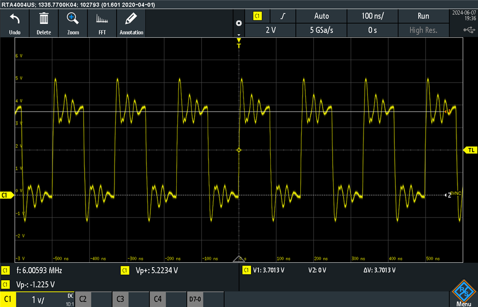
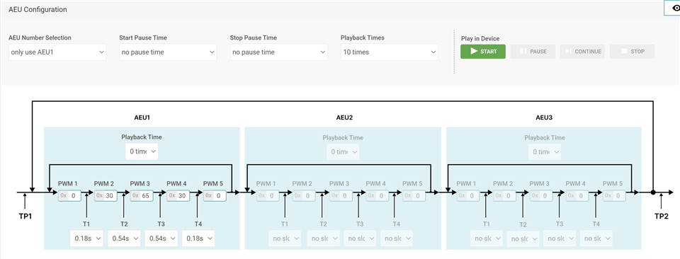
I am able to get SYNC signal between the ICs and I have attached a scope shot of the signal. I set a simple blinking animation for each of the parts through independent I2C communication, and then send a start command (start_cmd[0:0] to 0xFF) through broadcast I2C. Both devices start shining the LEDs, but the animation between devices quickly get out of sync after 5 playbacks.

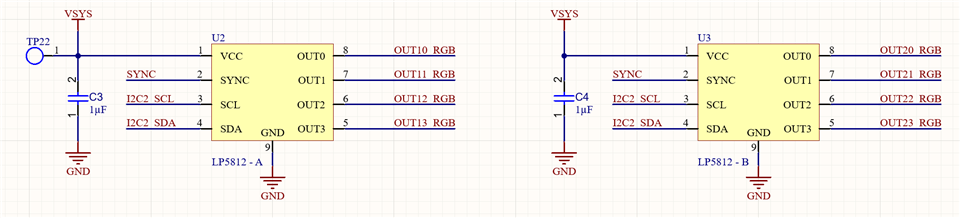
I am also attaching a screenshot of the schematic. I was wondering whether I am missing anything in the setup or missing any register settings. 

Thank you,

Rei

  • Hi Rei,

    Can you please tell me the detail step to use this sync function, especially for the register configuration?

    BR, Jared

  • Hi Jared, 

    I used the GUI to set devices up. As mentioned, here are the steps taken:

    Independent I2C at address 0x14:

    1 - In the Drive Mode window, I set the "LED Drive Mode Selection" to "Scan Drive Mode with 4 Scan Modes"
    2 - In the Device Configuration window, I set "Vsync Output Enable" to "Vsync is output". I leave the rest of settings in the Device Configuration window as default.
    3 - Click "Update Command"
    4 - In the Mode Selection window, set all LEDs to Auto mode and enable them. In Auto Mode configuration, I set a simple animation just to confirm correct operation using only one AEU. Attaching picture with animation settings.
    5 - Click "Update Command" and "Update"

    Disconnect from 0x14, and then connect at I2C at address 0x15:

    1 - In the Drive Mode window, I set the "LED Drive Mode Selection" to "Scan Drive Mode with 3 Scan Modes"
    2 - In the Device Configuration window, I set "Vsync Output Enable" to "Vsync is input". I leave the rest of settings in the Device Configuration window as default.
    3 - Click "Update Command"
    4 - In the Mode Selection window, set all LEDs to Auto mode and enable them. In Auto Mode configuration, I set the same animation just to confirm correct operation using only one AEU. Attaching picture with animation settings.
    5 - Click "Update Command" and "Update"

    Disconnect from 0x15, and then connect through broadcast I2C.

    1 - Using the Register Command window, I send 0xFF to start_cmd[0:0].

    All LEDs start blinking, but the group of 4 and group of 3 quickly get out of SYNC from each other. 

    Do you have a reference design or register map I can load in the GUI to try SYNC functionality or steps to follow? 

    Best regards,

    Rei

  • Hi Bel,

    our expert will reply once back to the offcie.

    BR

    Monet Xu

  • Hi Rei,

    I think there is no problem for setting sync function. Could you please check if the animation of 2 device is the same configuration?

    Or maybe you can save the register map configuration for the both slave address device separately and send it to me. Thanks!

    BR, Jared