Tool/software:
Hello everyone,
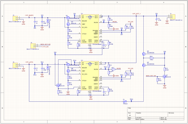
I have created a PowerMux Eval board and have now carried out the first tests. For this I followed the Priority Power MUX Operation (chapter 10.3.2) from the TPS2663x data sheet (SLVSE94F) and created a circuit diagram and board. Here are the states of the circuit.
Case 1: VMAIN = Input = 24V/4.5A; VAUX = Output (SENS_OUT = High, Q7 switched) = 24V/500mA (Sensor Output)
Case 2: VMAIN = OFF; VAUX = input = 24V/4.5A
UVLO ~ 4V; OPV ~ 33V
Now to the problem:
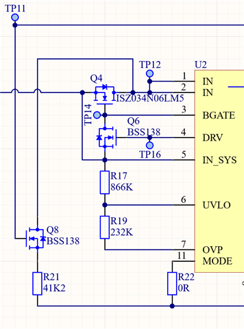
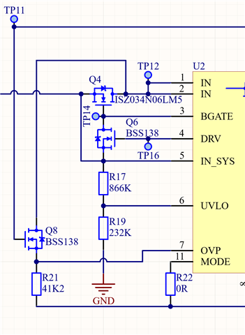
I supply my system with 24V via VAUX I also have 24V at VOUT, so far so good. But I have ~4.8V at TP3. But the voltage there should be 0V. I measure 4.8V at U1 pin 3 (BGATE) and 10V at U1-4. So that this Q2 switches.
In my case, there must be no voltage at VMAIN if U2 is the active power supply.
If I supply via VMAIN, I have the same problem at VAUX (TP11 ~4.8V).
Is this normal behavior of U1 that voltages are present at U1-3 and U1-4? Can this be prevented?
Unfortunately, I can't find any further information on this. I would be grateful for any help.