This thread has been locked.

If you have a related question, please click the "Ask a related question" button in the top right corner. The newly created question will be automatically linked to this question.

TPS62933EVM: Decoupling Caps placement consult

Part Number: TPS62933EVM
Other Parts Discussed in Thread: TPS62933

Tool/software:

Hi Teams,

I am designing with TPS62933 and have some questions about the caps placement at the input and output.

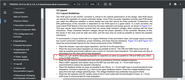
According to the description in datasheet layout guidelines, we'd better put small value cap as close as better to the IC pins.

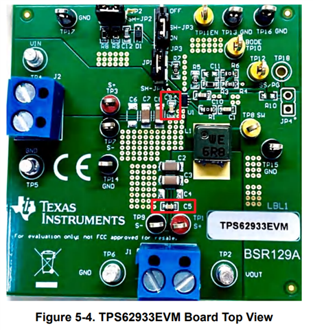
But I found that on the EVM, at the input, small value C9 is very close to the Vin, but at the output, small value C5 is not so close to the GND, but very close to the output connector.

Could you kindly help to clarify in the theory level to help me understand, do you have any appnotes addressing this part? If so, it also helps.

BRs,

Marsh

  • Hi Marsh,

    C9 which is 0.1-uF will be helpful for high frequency filtering and it's placed as close as possible to Vin pin. For C5, it's nice to have but no must required for TPS62933 itself. Generally the output of TPS62933 will be the input of the downstream. Thus, in order to provide high frequency filtering of the downstream load, it's also recommend to add it. That's the reason why you see it more close to the next stage but not much close to SW. 

    Hope it helps!

    BRs

    Lucia