This thread has been locked.

If you have a related question, please click the "Ask a related question" button in the top right corner. The newly created question will be automatically linked to this question.

TPS23755: Part fails when disconnecting secondary power

Part Number: TPS23755

Tool/software:

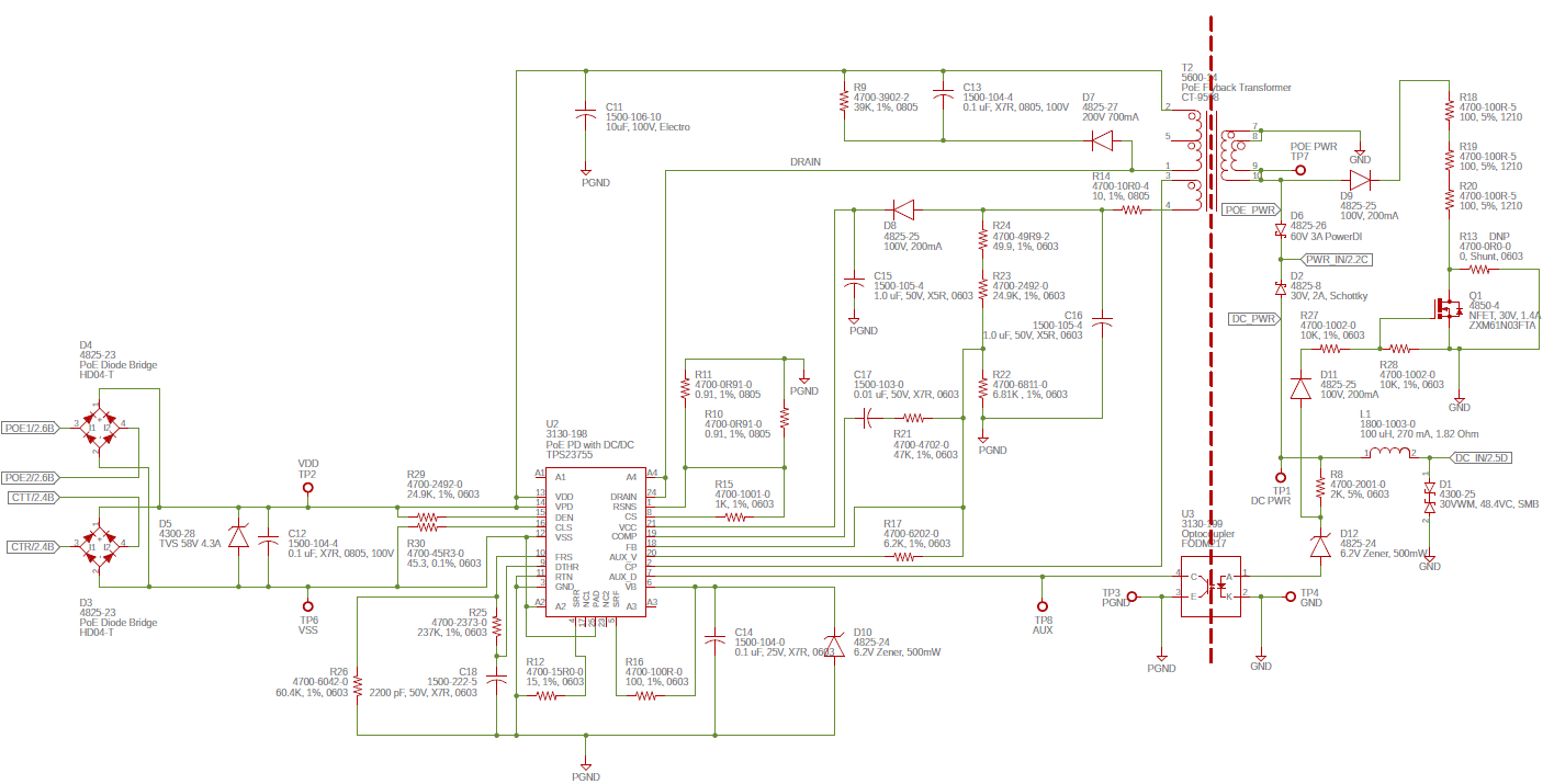
I have an isolated power supply design based off the 23755 reference design.  The POE power is working correctly.  I see it drop to the lower voltage when the secondary power supply is connected.  But when I remove the secondary supply, the switching stops and the chip gets hot and never works again.  

What could be causing the failure?  I have adjusted the setpoint resistors to give a 15V output instead of a 12V output.  Otherwise the circuit is the same as the reference design.

  • Hi Robert,

    PD Apps expert Diang is currently out of office on travel and will return tomorrow. Please expect a delay in his response, thank you for your patience!

    Regards,

    Brandon

  • Hi Robert,

    Thanks for your patience.

    Would you mind to share the schematic of your design? Thanks!

    Best regards,

    Diang  

  • Here's my schematic:

    The output voltage is about 13.9V.  The hotswap was working correctly at this voltage.  Then I changed R17 to a 4.3K Ohm to increase the output voltage to about 15V.  This is when the problem started when I remove the secondary supply.  Ideally I would like to provide a 24V output.  Could you please recommend any changes necessary to use the TPS23755 for a 24V output?  Thanks!

  • Hi Robert,

    Thanks for sharing the schematic. I will take a look and get back to you early next week.

    Best regards,

    Diang 

  • Hi Robert,

     Thanks for your patience.

    About the PD hot issue. I guess it could be mainly caused by lacking of capacitance.  

    1.There does not have decoupling capacitors on the DC/DC primary side. I would recommend to have at least one ceramic cap in parallel with C11 and can be layout close to T2.

    2.On the DC/DC secondary side, also no capacitors are shown. Please make sure you have adequate capacitance for dc link and decoupling. 

    3.It is recommended to use totally ~100 -150 Ohm resistance in dummy load to ensure the maintain power signature will be valid when adapter is connected and PoE is in redundancy.


    About changing the output to 24V, you need to find a suitable 24-V output transformer can support PSR first. Make sure your turns ratio of SEC:AUX = 2:1, so that you can have 12V on the auxiliary side. Normally no further changes is needed on the primary side. And your secondary side circuit needs to be changed accordingly. 

    Best regards,

    Diang

  • Hi Diang,

    Thanks for the reply.

    1.  I will add the decoupling cap.

    2.  I have two 22uF 25V capacitors on the PWR_IN net, they are shown on another page of my schematic.

    3.  I will try to change my load to about 150 ohms.

    Regarding the 24V operation, I am using the recommended transformer.  It has a ratio of 2.25:1 between the primary and auxiliary winding, and a 2.57:1 ratio between the primary and secondary windings.  Wil this transformer work for 24V?  What changes are needed on the secondary side?

    Thanks for your help,

    Rob

  • Hi Robert,

    Thanks for your quick reply.

    In this case your SEC:AUX =  1 : 1.14, which will cause VCC voltage 24V * 1.14 = ~27V. For PSR, we normally want the VCC 11 - 16V. Thus it is not good for 24V output application. 

    Besides a flyback transformer in PSR application needs a better coupling between AUX and SEC than the normal transformer. POE13F-24L has the correct turns ratio, but it is better you can check with the vendor about the PSR capability too. 

    Best regards,

    Diang

  • Hi Diang,

    I'm looking at the spec for the POE13P-24L transformer you mentioned.  It looks like the SEC:AUX ratio is 0.75, which would require a 18V VCC to maintain the 24V output.  This is over the recommended range for VCC.  Am I calculating this correctly?  

    Thanks,

    Rob

  • Hi Robert,

    Thanks for your correction. You are right POE13P-24L's turns ratio is not suitable here...

    POE13F-24L's turns ratio looks correct for this application. When Vout = 24V, VCC = 24/2 = 12V.

    Best regards,

    Diang

  • I think the reason the part was failing was because I was exceeding the max VCC voltage with the original transformer.  I tested the circuit with the new transformer and have stable operation at 24V.  Thanks for the help.