Other Parts Discussed in Thread: LM5164
Tool/software:
Hello Sir or Mam
Hope you are doing well
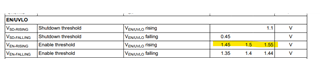
There is one issue regarding the Undervoltage cut-off and the output voltage of Buck converter LM5164.
Main Application: In this particular query, we do have 2 boards, one is the FCT board and the other is IOT device. Here we are powering the IOT device with FCT board which consists of two buck converter circuits, One is for providing under voltage and the other is for providing over-voltage. The FCT board consists of two buck converters to test the Undervoltage cut-off feature of the LM5164 which is implemented on the IOT device.
Image 1 : Consists of 2 buck converters on FCT board
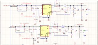
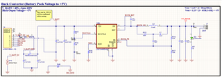
Image 2: Consists of Buck converter in the IOT device
Testing we have to do: Now the case is we have 100 IOT devices on which we have to test the functional testing. In the functional testing, we test the UVLO feature of the Buck converter by which the IOT device gets on or off.
Inputs:
The IOT device->
--- cutoff voltage is set to 43V before diode D5 (in Image 2),
--- The actual cut-off voltage after diode D5 is 42.57V at the VIN pin of the buck converter (in image 2).
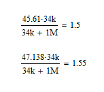
--- According to the calculation the Turn On voltage for this UVLO is 45.61V after diode D5 (in Image 2)
--- And before the diode D5 it is 46V (in Image 2).
Note: There is drop of 0.3 to 0.4V drop of this D5 Schottky diode (in Image 2)
The FCT device->
--- One Buck converter output is set to +41V to test the under-voltage cut-off feature, and by giving this supply the IOT device gets turned off.
--- The other buck converter output voltage is set to +46.36V, and by giving this supply the IOT device gets turned on.
The issue that we are facing :
From those 100 devices, there are 10 devices that are not getting Turned ON during the test, as during the turn-on process we are giving 46.36V which is greater than the 46V, therefore, the IOT device should get turned on.
Steps taken by us->
--- All the components are correctly soldered, and no soldering error is there
--- The values of all the components in the Buck converter circuit are also identical.
--- Reflow on the PCB is also done during the debugging process.
But still, those devices are not getting turned on.
Kindly look through this problem.
Looking forward to hearing from your side.