This thread has been locked.

If you have a related question, please click the "Ask a related question" button in the top right corner. The newly created question will be automatically linked to this question.

CSD17484F4: MOSFET Delay Times Not Appearing in Pspice Model

Part Number: CSD17484F4

Tool/software:

Hello,

I am trying to verify the timing data for the CSD17484F4. I am using the unencrypted Pspice model given for this device in a Cadence Virtuoso testbench. This testbench is meant to replicate the test conditions used within the spec sheet to generate the timing data. Below is a screenshot of my test bench:

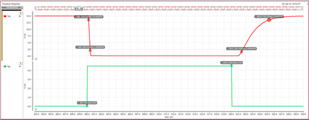
The gate is driven by an ideal square wave voltage source that pulses between 0 and 4.5 V with 50ps rise and fall times. The drain is biased with a 15 V dc source and is paired with a series 30 ohm resistor to limit the drain current to 0.5 A. Below are the results of the transient analysis:

Comparing my results with the numbers given in the spec sheet, I find the following:

Transient Sim Spec Sheet
Turnon Delay Time 200ps 3ns
Rise Time 200ps 1ns
Turnoff Delay Time 1ns 11ns
Fall Time 3.8ns 4ns

Can someone please help me understand why my testbench is much faster than the data given in the spec sheet? Should I expect the MOSFET to perform more closely to my modeled results or the spec sheet results?

Thank you for your time,

Braden

  • Hello Braden,

    Thanks for the inquiry. The switching times in the datasheet are measured on a board with a gate driver IC and a 2Ω gate resistor. This data was collected during product development. Unfortunately, I do not know what gate driver IC was used for testing the CSD17484F4. Gate driver ICs have limited current drive capability and normally spec pull up and pull down resistance values (from < 1Ω up to a few Ω) in the datasheet. Switching times in the MOSFET datasheet are very dependent on the PCB parasitics and external gate drive circuit as detailed in the blog at the link below. There is also a video training of this material that I have found to be much more informative at the second link below. You can add an external gate resistor to your simulation as well as the pull up and pull down resistance of the gate driver (try 1Ω or 2Ω). Let me know if you have any questions.

    https://www.ti.com/lit/ta/ssztch1/ssztch1.pdf

    https://www.ti.com/video/5108350697001

    Best Regards,

    John Wallace

    TI FET Applications