This thread has been locked.

If you have a related question, please click the "Ask a related question" button in the top right corner. The newly created question will be automatically linked to this question.

UCC28750: Full load startup issues

Part Number: UCC28750

Tool/software:

Hello, I have designed a power supply using UCC287506 to be operated on 100kHz, 12 watt output power. I am facing an issue during startup at full load. My observation is that during startup the controller is switching at 50kHz, which is causing it to trigger over power protection.

I tried to reduce the Rcs (2.2E || 2.2E) by half during turn on and changed it back to the original vale (Rcs = 2.2E) then the circuit is working. But when im keeping RCS = 2.2E the circuit is going in hiccup mode.

  • Hi Himanshu,

    Thank you for reaching out.

    Yes it is possible to hit over power threshold because, FB is maxed out and if duty is greater than 60% and the FB signal mostlikely higher than OPPP ramp it can trigger OPP. going into hiccup mode.

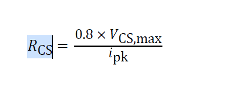
    The UCC28750 should be designed so that CS pin is designed with sufficient headroom as mentioned in the datasheet allowing for sufficient margin for transients/ startup currents.

    Regards,

    Harish

  • Hello Harish,

    Thank you for the quick response. In the datasheet the headroom mentioned is only 20%.

    I tried reducing the value to 1.8 ohms still im observing the same issue. If there is anything else im missing please guide me.

  • I have a taken a trial with 1.5 Ohms as current sense resistor. My observation are as below:

    Input Voltage Rcs = 2.2E (Without slope comensation resistor) 1.5 E with slope compensation 1.5E without slope comensation
    140 V Startup issue Startup ok, i/p pwr 14 watts Startup ok, i/p pwr 14 watts
    180V Startup issue startup issue Startup ok, i/p pwr 14 watts
    240V Startup issue startup issue Startup ok, i/p pwr 14 watts
    270V startup issue startup issue Startup ok, i/p pwr 14 watts

    waveforms for reference. Green Waveform : Across Rcs, Yellow waveform = after slope compensation resistor (Across the 56pF cap).

    ...

    Slope compensation resistor = 1k, capacitor = 56pF.

    I have observed one more issue. I'm not able to use over voltage protection. I have connected 3 resistors of 1.5 Mega in series with a 47k resistor for overvoltage fault detection across the 47k, (it should read around 4 volts @ 270 vac input). But as per my observation the fault pin is somehow clamped to 2.45 volts and the voltage is not varying irrespective of the applied input voltage.

  • Hi Himanshu,

    Thank you for the reply.

    It looks like from the waveform, Vcs hits greater than 900mv and if this happens for 8 switching cycles during startup, the IC will trigger shutdown. The effect will be more as the voltage is increased with increasing load.

    I think is what is happening in your case.

    Regards,

    Harish

  • Is there a way to reduce that spike? Because Coss and other parasitics are beyond our control. 

  • The only way could be to put capacitor as close as possible to the CS pin, maybe directly across the pins 1 and 4 and try values from 22pf upto 200pf to see if this helps.

  • Hi Harish, I tried connecting a 180pF capacitor across the Current sense pin. It working now even with 2.2E resistor. Can you share the significance of increasing the capacitor value? Is it simply to give noise immunity? or to slow down the rise of current sensed voltage & avoid nuisance tripping?

  • Hi Himanshu,

    Thank you for the reply. Good to know that the capacitor is able to help with the startup issue.

    Too much high capacitance can basically cause delay where higher peak current is reached. But as long as the transformer has sufficient headroom for saturation current, this should not be a cause for concern, 

    This problem is primary due to noise getting coupled to CS pin. Maybe you check with slowing the DRV signal if this help, but I doubt. The capacitance will inevitably be needed.

    Regards,

    Harish