This thread has been locked.

If you have a related question, please click the "Ask a related question" button in the top right corner. The newly created question will be automatically linked to this question.

TPS23861: No classification event after 3rd device has been attached

Part Number: TPS23861


Tool/software:

Hello,


we experience a strange behavior where the TPS23861 does not perform a classification event, if multiple devices are attached. The general error path looks like this.


The TPS is working in Semi Auto mode.

Attach a PoE sink to “Port 1” of the TPS – Sink will be powered.

Attach another PoE sink to "Port 2" of the TPS – Sink will be powered.

Attach a 3rd PoE sink to “Port 3” of the TPS – Sink will not be powered.

Attach a 4th PoE sink to “Port 4” of the TPS – 3rd and 4th sink will be powered.

All PoE sinks are of the same type and are Class 2 devices.


There are other combinations that lead or resolve the error as well. But the depicted case is the most reliable one. Our measurements show that the TPS is not performing a classification event on Port 3 in this case. Instead, the 4-quadrant measurement is repeated as a loop. We also do not see any changes to the chip registers happening while the PoE sink device remains unpowered.

To make the error more complex. It does not always happen. There are some PoE sinks that seem to trigger the error, while other identical PoE sink combinations works flawlessly. The error does not occur in Auto mode. But due to software restrictions we must use the Semi Auto Mode. All devices, as well as our TPS23861 hub have been tested for 802.3af compliance via dedicated compliance testing equipment.

When we checked the PoE signals on the sink, we did not see any difference between good and bad cases. The only irregularity we see is a different behavior in regard of the number of classification events. While the datasheets stated that in Semi-Auto mode a single classification event should be performed for Class 0-3 devices, we see two events like it should be the case for class 4 devices. But this seems to happen regardless of the used PoE sink. We have seen this behavior for multiple different vendors and chipsets, while all the used PoE sinks where class 2 devices.

Therefore, it seems that we still have a problem with our implementation. Could you elaborate what exactly happens during the 4-quadrant detection event? What timings, voltage levels and requirements are need by the TPS to trigger a classification event?

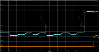
To give you some additional insight, here some of our measurement results. Blue is the PoE voltage at the sink, behind the full bridge rectifier didoes. Orange the output voltage of the PD chipset in the sink device. 

First a "regular" power up event. As you can see, the classifcation event is performed 2 times, instead of a single event. 

Then for comparison the same device in auto mode, where only a single classification event is seen.


An the last measurement shows the error case where no classification is happening at all. Green and yellow can be ignored, as those are diffential signals used for the blue math function curve. 


Yours faithfully

Christopher

  • Hi Christopher,

    I will take a look at this tomorrow and get back to you with my feedback. Thanks for your patience!

    Regards,

    Brandon

  • Hello,

    is there any feedback you can give us regarding this problem or do you need additional informations from our side?

    Best regards

    Christopher

  • Hi Christopher,

    Thank you for your patience! 

    There are a couple things here I want to point out, multiple detection cycles is actually a good thing and all the issues you are seeing seem to be a host FW driver. Basically whatever MCU/CPU you are using to control your system, but first lets take a look at how detection and classification on the port occur.

    1. Detection:

    Detection uses a control current sourced out of the DRAINx pin accross the pairset which is then sunk by the far end PD's detection resistor (typically 25kohm). This creates a voltage differential on the pair, which is then captured by the PSE to calculate the PD's valid detection resistance is within the acceptable range. Our PSE devices use a 4-point detection method to ensure the validity of the PD on the far end, which is why you see 4-point detection in both auto and semi-auto mode.

    2. Classification

    If classification is enabled on the PSE, the classification cycle will only trigger once the PSE sees a valid detection result. In both of you captures above, everything looks normal as your classification cycle always triggers in both semi-auto and auto mode.

    For 15W PD devices (Class 0-3), you will see one finger classification, which is confirmed in your screenshots above. Those both look normal.

    3. Turning on the port: 

    My guess as why for some reason your port is not being turned on before another detection/classification cycle is because per specification, there is a Tpon requirement which the port must be turned on within 400ms of a valid classification cycle. If this is not met, then the device will do another detection classification cycle and wait for power on command.

    One-event classification:

    One event classification:

    Specification for power on requirements:

    Next steps, confirm the PD is a class 1 PD. It seems it is but confirm.

    Next step: check your control loop in your FW for reading the detection/classification event and issuing turn on. I am assuming you are getting stuck when the 3rd port is not turning on, step through the FW to confirm.

    Regards,

    Brandon

  • Hello Brandon,

    thank you for the feedback, I will double check with the SW department. My current understanding is, that we do not see any register changes when the 3rd antenna is attached. Is this case we can not know, when to turn on the port, right? But let me double check before we jump to conclusions. 

  • Hi Christopher,

    It should be enabled through your interrupt handler, when a detection/classification cycles successfully occurs it will trigger an interrupt which your handler would then check which interrupt then which port status changed. 

    Since in auto mode this works with no issues, I am almost certain it would be a FW related bug from your host system. Please confirm and let me know!

    Regards,

    Brandon

  • Hello Brendon,

    I had a talk with our SW department. They are using the TI source code to handle the TPS chip. The embedded Linux routine we use is Interrupt based. And the reaction time should be fast enough. 

    So we decided, that we read out the whole TPS registers each time we attached a new sink. Attaching the first and second sink, the register changes seem plausible. After attaching the 3rd sink, the TPS indicates detection resistance to high for port 3. Interesting.  

    With this information I would assume that the SW is working correctly. What I don’t understand, why do we not see this behavior in auto mode and why does attaching a 4th sink or removing the first or second sink resolve this issue?

    If the detect resistance is too high, it should always be to high and not suddenly be correct if I attach or remove additional sinks. Is there a difference in how the chip handle the resistance measurement between full auto and semi mode?

    Another point might be coming from the datasheet, where for the detection resistance the following is specified:

    Accepted resistance range 19 – 26.5 kOhm

    Rejected resistance high range 33 – 50 kOhm

    What happens in between? Is the chip behavior not defined in this range?

    Best regards

    Christopher

  • Ok, clicked on the wrong field. The topic is still open and I have some additional measurments. 

    I did some more testing and focused on the detection resistance. Our sinks have a 24.9 kOhm detection resistance. If I test the sinks one by one, the TPS measures for each of them a value near 25 kOhm. So this is fine. 

    When it comes to the error case. I can attach the first two sinks. They are measured at 25 kOhm.

    The third think is measured around 29 kOhm and is not powered.

    The fourth sink measures at 19 kOhm and is powered, while also the third now powers up and measures at 28 kOhm.

    If I switch the TPS to full auto mode I get different measurements for the detection resistance.

    Sink 1 and 2 around 25 kOhm

    Sink 3 and 4 closer to 26 kOhm

    This is below the data sheet specification of 26.5 kOhm and might be the reason why in full auto mode our sinks are always powered.

    What I don’t understand is why the TPS shows this different behavior in its modes and why it measures wrong values in the first place. Could this be a layout issue?

  • Hi Christopher,

    I agree with you this is strange behavior and there should be no change in the detection/classification result when switching between semi-auto and auto modes. 

    Let me run this scenario on my side in the lab and check the results. I will feedback tomorrow with my test results.

    Regards,

    Brandon

  • Good morning, Brandon,


    we have continued our debugging sessions and another interesting measurement result occurred. When we attach all 4 sinks at the same time and then power on our TPS chipset, all resistance measurements are always correct.

    Can you elaborate what exactly happens upon first power up? If I’m not mistaken the TPS is always configured in auto mode after reset? Are the default semi auto mode settings in the port registers ignored in this case? Sorry I’m not completely into the SW workflow. When does the TPS perform the fist measurement? Is it in auto mode or will it wait until the TPS was configured via I2C before the first measurement?

    In our software, the init procedure is a following:

    • Enable 48 Volts.
    • Wait for 48 Volts to became stable.
    • Toggle TPS reset pin and wait 50 ms.
    • Read TPS device ID to ensure that the chip is accessible.
    • Configure Chip to semi auto mode.
    • Turn off all ports and re-enable detection and classification.
    • Enable interrupts for all events.


    Since our sinks stay powered with correct resistance measurements values after this procedure. I would guess that the chip did not perform a measurement prior to our init routine. Therefore I see no reason why the measurement values should decay when I dis- and re-attach the sinks after this fist power up.

  • Hi Christopher, 

    Thanks for your reply.

    Brandon is currently out of office and he will be back in the next week. Please expect a delayed response. Thanks for your patience!

    Best regards,

    Diang

  • Hello together,

    any update regarding the question why the TPS is measuring different resistance values in different modes? 

    We do think that we identified a stray current through the RJ45 shield as part of the problem. Unfortunately, we do not understand why a current should be flowing through the RJ45 shield in the first place. And especially we do not understand why the first manual measurement always returns correct            resistance values, while later measurements do show higher values with each attached sink. Or why those same measurements in auto mode result in lower resistance values. From our point of view the software should not have in impact the path the current chooses trough the system.

    Best regards

    Christopher