TPS56837: TPS56837RPAR

Part Number: TPS56837

Tool/software:

Hi,
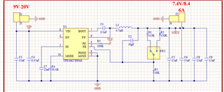
I designed a buck converter based on TPS56837RPAR.

I connected a RC servo motor as a load and after applying overload. The buck converter stopped working.

As this chip is supposed to have OVC,UVLO,OV protections

I need to know the following


  1. What can cause to damage the board permanently?

  2. What tests, i need to do to find the exact issue that causing the problem? I did tests with electronic load tester but it work there upto 8A as desire. As electronic load tester has builtin safety function so it turn off when there is some issues. I need to perform tests with real load to find the problem that causing to fried buck converter board so i can add protection for it

This is the schematic of the circuit

  • Hi Ali

    Can you please share the layout image? And please share the part number of the L1?

    Will SW1 function during the test?

    What phenomenon the damage is? Can you measure the damaged device with multimeter and see if there are short-circuit between VIn, SW, GND pins?

    Yes the device has OCP protection, you can short the VOUT and GND together and it should be able to enter the hiccup mode.

     Can you reproduce the damage? By connecting the real load, and catch the waveform at the time it damages using the trigger function of the oscilloscope. You can trigger the down-slew-rate of the Vout, and record the waveform of Vout, SW, Vin. and iL if possible.

    Thanks and best regards.

  • Hi
    Can you share your email so i can send you complete project files of Altium?

    I will also share a test video there with you.

    Thanks

  • Hi Ali

    Please send email to bella-he@ti.com 

    Thank you

  • Hi

    I sent PCB files at your email.
    The videos are long so aren't able to send.
    I explain here so far what i found


    1. When connecting or disconnecting a servo while the power is ON, the buck converter gets damaged after a few attempts. This issue was not observed with a different market buck converter under the same conditions. It is important to note that the motor is not running during the plug/unplug actions; simply connecting or disconnecting the servo causes the buck converter to become damaged.

    2. Furthermore, when the motor is overloaded, it sometimes causes the buck converter to restart. Occasionally, on the first attempt of overloading, the buck converter gets damaged. The motor in use is a standard RC servo motor.

  • Hi Ali

    Thank you. Let's keep on the email page and I will close this thread now. 

  • Hi
    I am not getting your response so i am asking here the questions

    1: I need the answer to this question or the way to test it so i can provide further information.

    1. When connecting or disconnecting a servo while the power is ON, the buck converter gets damaged after a few attempts. This issue was not observed with a different market buck converter under the same conditions. It is important to note that the motor is not running during the plug/unplug actions; simply connecting or disconnecting the servo causes the buck converter to become damaged.

  • Hi Ali

    Sorry for the late reply. Can you please share the part number of L1 and the Isat ?

    Thanks and best regards.

  • Here is the inductor part number
    XAL6060-472MEC

    www.mouser.ca/.../XAL6060-472MEC

  • Hi Ali

    Does the damage only happen when start up with over load , or also happens when increase the load under steady Vin?

    During start up the iL can be large and hit the peak current limit, especially when start with large load &when there is large output capacitor, can you please measure the iL, Vin, SW, and Vo during start up? 

    You can try replacing with a inductor with higher Isat and see if it helps.

    Thanks and best regards.

  • Hi
    The damage happen when i simply connect load(motor). Motor is not running in this stage.
    Simply connect motor power wires with the buck converter output and unplug it.
    The buck converter is power up though during this process.
    see the attached video

  • Hi Ali

    Can you please test with oscilloscope and attach the waveforms? you can measure the Vin, SW,  Vo ,Io .

    Thanks and best regards.

  • Hi Ali

    Do we still have the problem now?

    Thank you.

  • Hi Ali

    I will close this thread now, please let me know if there is still questions.

    Thanks and best regards.

  • Hi 

    Sorry, i was traveling so couldn't reply.

    Actually I can't provide waveform because i already damaged all boards in testing.

    What i noticed during testing that if i apply load current above 9A using load tester then it get damage. Now i couldn't figure out the problem when apply force on the motor.

    I guess what i needed is load current limiter that can sustain output current at 8A and even if load demand more current. It keep it within limit.

    I am also open to use other IC for same application.

    Thanks 

  • Hi Ali

    Do you mean the damage can happen under steady load of 9A?  the SW1(Vo select switching) do not operate during this test, right? What's the Vin voltage?

    Can you please try adding a 0.1uF/0603 ceramic capacitor close to Vin and GND pin? You can add it in parallel with C4. And see if this could help.

    It would be helpful if we can track the waveform of SW/ iL .

    Thanks and best regards.

  • Yes,

    It tries to shutoff at around 9A like reset but if i raised the load current to around 10A then it permanently damaged. I was using load tester so it was pretty constant current 

    This make sense though because it is supposed to be max 8A.

    My major concern was connecting and disconnecting motor with it permanently cause damage. You probably already see that in the video.

    Motor wasn't spinning. Just plug in and plug out damaged it.

    Now i wonder if it is light load condition or reverse current so i want to add something for protection at output side.

    Thanks 

  • Hi Ali

    Actually ,8A is the allowed max continuous output current, it has overcurrent protection and should not damage under over current condition or output-short-circuit condition.  

    Do you have a current sensor that we can catch the load current waveform when connecting and disconnecting the motor? That can be helpful to identify the root cause. 

    Thanks

  • Yes, but it's overcurrent protection seems like not work as it should be. It only work up to 9A and if load current is above that. It simply get damaged.
    I have oscilloscope now but unfortunately, i already damaged all boards so I can't test anything now.
    I need a fool proof solution for next revision.
    The main thing is the board size.
    I have only 20x15mm board size available.
    Height is also important but if I had no other options then i can have little flexibility in height.

    I need a solution asap.
    The input voltages are in the range of 9 to 20V. The output will be 7.8V/8.4V(switchable using a switch).

    Thanks

  • Hi Ali

    TPS5837 is the most proper device for this Vin Vo Io application.

    Will you be able to replace the IC on the board to test& debug?

    We can have a brief meeting if needed.

    Thank you

  • Hi
    It would be great if we can discuss on the meeting.
    Can you provide me a timeline available in this week?
    I usually available at 9 to 11AM EST
    Thanks

  • Hi Ali

    I have sent you a meeting calendar.

    BR.

  • Yes, received 

    Thanks 

  • Hi Ali

    I close this thread for now, let's keep on the email page. 

    Thank you!