Other Parts Discussed in Thread: TIDA-050014
Tool/software:
Hii,
We want to design a DC-DC converter with an input voltage of 12-24 V and a variable output voltage of 12-20 V, how can we do it with LM25143?
This thread has been locked.
If you have a related question, please click the "Ask a related question" button in the top right corner. The newly created question will be automatically linked to this question.
Tool/software:
Hii,
We want to design a DC-DC converter with an input voltage of 12-24 V and a variable output voltage of 12-20 V, how can we do it with LM25143?
Hi Abishek,
Variable output how? As in if VIN = VOUT when VIN<20V, and then VOUT = 20V when VIN >= 20.
Or do you want to be able to change it on the fly?
Thanks,
Andrew
Hi Abhishek,
I recommend using the LM25143 quickstart calculator: https://www.ti.com/tool/LM5143DESIGN-CALC
Set Vout = 20V first and derate the ceramic output capacitance accordingly. Then fix the compensation values and check the loop with Vout = 12V and the higher Cout value for 12VDC. The crossover frequency should not exceed ~12% of Fsw or 100kHz, whichever is lower.
Regards,
Tim
No, the input supply voltage will be 24 V from the battery, and we need a variable output voltage between 12-20 V by controlling its duty ratio.
Hi Abhishek,
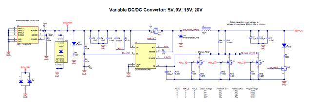
It's technically possible, but this will increase circuit complexity as control signals and MOSFETS are required in order to enable/disable the resistor feedback network to achieve variable VOUT.
TIDA-050014 does this by having a control signal turn on/off various mosfets in the resistor feedback network.
https://www.ti.com/tool/TIDA-050014

Thanks,
Andrew
In addition to what Andrew mentioned, you can also use a PWM signal from an MCU that is averaged by a couple of RC filter stages and then resistively coupled into the FB node to continuously adjust Vout over the required range.
See Fig. 10 here: https://www.ti.com/lit/an/slyt777/slyt777.pdf