This thread has been locked.

If you have a related question, please click the "Ask a related question" button in the top right corner. The newly created question will be automatically linked to this question.

TPS61178: Help solving stability problems under load, and webbench calculates different COMP values than datasheet example...

Part Number: TPS61178

Tool/software:

Hi,

I am using a TPS61178 to provide 13V to 17V boost, Iout~2.5 Amps. At light load the supply is stable, but at 2.5 amps the behavior is eradicate, sometimes stable other times the inductor squeals and the output voltage is only 15V.

The design was based off the datasheet example since the input/output parameters are similar to application.

Datasheet for TPS61178 provides reference design for Vin 6-14V, Vout=16V, Iout=3A, F=300 kHz. The schematic on pg16 Figure 22, shows the recommended component values. 

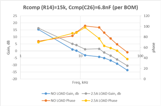
L=1.8 uH, Cc=6.8 nF, Rc=15k, Cp=10pF. F=500kHz. A table of inductor choices ranging from 1.8 uH to 10 uH is also provided.

The topic design uses nearly identical to the datasheet example:

L=4.7 uH, Cc=6.8 nF, Rc=15k, Cp=N/A. F~480 kHz. Note Cp is not included. 

Using webbench (6-14V input, 3A@16V output), recommends component values:

L1=2uH, Cc=180 pF, Rc=249k, Cp=N/A

I am going to add the Cp=10pF and re-evaluate the circuit behavior. But in the meanwhile, any comments on why webbench recommends COMP values that are so different than the datasheet?

  • Hi Bradley,

    The datasheet parameters are more reliable.

    For webench result, it may work but there could be some deviations

    Please check if your inductor's saturation current is enough for your appliaction.

    Also, the output capacitance needs to be checked to ensure a same loop gain like in datasheet.

    Best Regards,

    Fergus

  • Thank you for the fast response and advice to use the DS values. 

    Inductor rating is Isat_max = 9.3A, Irms_20C = 8.5A, DCR=14.4 mR. 

    TPS61178 current limit R= 180k --> 4 amp max. In the full circuit, Iout max will be only 1.5A.

    I have been testing at 2.2A (not 2.5A as stated above) to ensure adequate margin.

    Caps:

    DS example shows 2x 10 uF and 3x 22uF, PNs or derating information. EVM BOM has 22uF caps, Murata website indicates -75% derating at 17V (3x5.5 uF)

    Topic design is using 3x 22uF/25V/X7S (5mR each) (-40% at 17V) = 3x 13uF, so Cout is 2.3X EVM and DS. 

    Is a spreadsheet calculator available for this part? ie to automatically (wo/ errors) perform design parameter calculations in 9.2.2?

    I was able to manually create some bode plots with the DS COMP values and some small shifts (graphs are all same axis limits and scales to facilitate comparison):

  • Hi Bradley,

    Sorry, there is no calculation tool for this device, but I made a mathcad file for it.

    I can send this to you if you want.

    In my calculation, the loop seems stable with the output capactiance.

    I doubt if the current limit is enough as the peak current is : Iavg+1/2*Iripple

    17*2.5/0.9/13+1/2*1.8=4.5A,

    Also, the device's current limitation will vary with +-1.5A.

    Best Regards,

    Fergus

  • Hi Fergus,

    Can you confirm the COMP values you used that resulted in stability?

                   did you include Cp?

                   if you did include Cp, does removing it prevent stable loop? 

    The current limit hypothesis will be investigated and I will let you know the results. 

    Yes please send me the mathcad file it will be very help. 

    Regards,

    Brad

  • Hi Brad,

    The Rc and Cp produce the compensation pole, it is usually used to decrease gain at high frequency.

    When Rc is15kohm and Cp is 100pF, the pole is 1kHz, which will not influence the loop much.

    Usually, the cross frequency is no higher than either 1/10 of the switching frequency, ƒsw, or 1/5 of the RHPZ frequency, ƒrhpz.

    Here the fsw is 480k and frhpz is 109k and the cross frequency needs to be lower than 20khz.

    As a result, in this case, Cp with small value do not help much about the loop.

     Please tell your email address so I can send it to you.

    Best Regards,

    Fergus

  • Hi Fergus,

    Is there additional data / information available about the efficiency of TPS61178 versus switching frequency?

    I was thinking to estimate efficiency based on FET losses (conduction vs switching), however the datasheet only provides Rds(on), but not Td(on), Trise, Td(off), Tfall, and diode recovery charge Qrr.

    Thoughts?

  • Hi Bradley,

    It is hard to calculate as it is also unknown to us about the Td(on),Trise and so on.

    We do not have the valid efficiency data on hand with different frequency, either.

    Would you mind if I have some efficiency tests on EVM for your reference with changing the frequency?

    You can tell me the input, output condition and desired frequency to me.

    Best Regards,

    Fergus

  • Your offer is very generous and would be tremendous help. I am looking for the general trend of how frequency impacts efficiency. I am hypothesizing that the efficiency is upside U shaped, with the peak occurring at the freq which balances the various losses (ie conductance, switching). The datasheet does have a few graphs on efficiency, Fig 1-5. Since my application conditions are similar, for the sake of continuity, I would suggest using similar/overlapping conditions as in those graphs.

    Specifically:

    Vout=16V, L=3.3 uH condition, 1~2 amp output, could be tested for a range of frequencies, 300 to 1Mhz.

    Additional data series with increased inductor value, within the same MFG & size series, say L=4.7 uH, and 5.6 uH, would also be very helpful.

    Thank you,
    Brad

  • Hi Brad,

    I will have a rough test for you and reply later.

    Best Regards,

    Fergus

  • Hi Brad,

    Please see the efficiency vs switching frequency.

    All the test is based on EVM parameters.

    eff test.xlsx

    it meets my estimation that when switching frequency is higher, the efficiency will be lower.

    The device's switching loss is proportional to the frequency, and it will be the main part of the loss.

    For the inductor, the loss is hard to estimate as it relates to many factors.

    Right now, the efficiency is undone because we do not have the inductors with same package and enough current derating.

    Below is a document we get from CYNTEC for your reference.

    core loss_TI_104 and 105_2R2 to 4R7.xlsx

    You can see even with the same package; the loss is quite different with different inductance and different part.

    The total loss is quite small so that the total efficiency goes down with the frequency.

    In your side, the inductor could be totally different case.

    Best Regards,

    Fergus

  • Thank you for the testing. The efficiency numbers are very close to those shown on the datasheet FIg 1(~95%, 6V input, 3.3 uH, F not specified).

    On my slightly modified EVM, I got E=98.4% at Vin=8.88V. I swapped the output caps for those with better dc bias derating, but default inductor.

    I've ordered a set of same size-code inductors, once they arrive I will repeat this Eff test, varying F and I, and will let you know results.

    Brad

  • Hi Brad,

    the datasheet data's frequency is 500kHz.

    I will wait for your result.

    Best Regards,

    Fergus