This thread has been locked.

If you have a related question, please click the "Ask a related question" button in the top right corner. The newly created question will be automatically linked to this question.

LM25185: LM5185EVM-SIO Altium project pcb, how AGND and PGND are connected ?

Part Number: LM25185
Other Parts Discussed in Thread: LM5185EVM-SIO,

Tool/software:

Hi e2e

Could you share the LM5185EVM-SIO Altium project pcb?

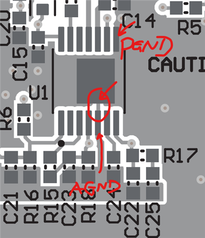
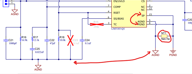
I ask becouse in document SNVU869 is not cleared for me with this information or I not found it on that document. For spec. LM25185 on basic schema I see AGND and PGND are connected but in which point and how ?

  • Hi Damina,

    Thank you for posting.  Since I will need our PCB craftsman to clean the file before sharing, let me see if I can answer you in this short reply.

    The AGND and PGND are connected through the under pad, which I highlighted in below:  the trace from the AGND pin to the under-pad.  PGND pin is beside the C14 label.  This small trace--which is represented by the Net-Tie on schematic--makes the single point connection between AGND polygon and PGND plane.  

    Hope this helps.

    Best Regards,

    Youhao