This thread has been locked.

If you have a related question, please click the "Ask a related question" button in the top right corner. The newly created question will be automatically linked to this question.

LM5122: OVP circuit- SSZT626

Part Number: LM5122
Other Parts Discussed in Thread: LMV431

Tool/software:

Hi TI Team,

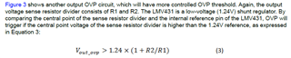
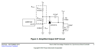
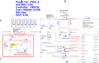
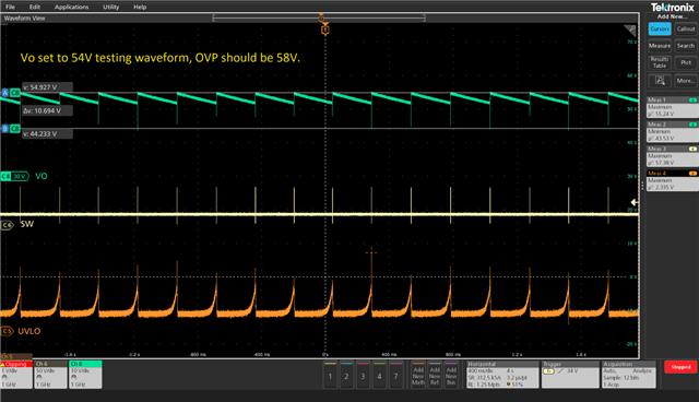
I follow TI's circuit and apply in our design for Over Voltage protection, in Vout=54V application, R1=10k (PR191), R2=453K (PR192), OVP setting point should be 57.412V (Eq.3)

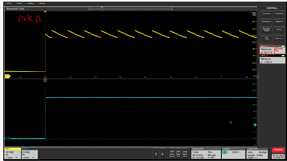
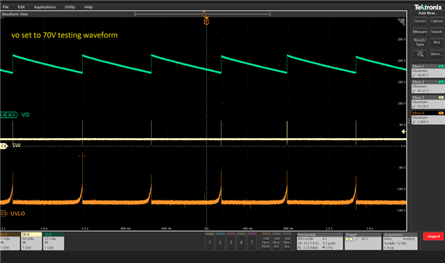
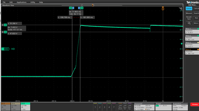
In real test, why the Vout clamp in 68.11V?

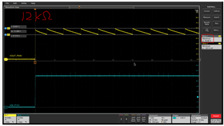
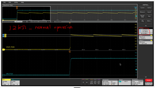
Since our OVP target is clamp Vout<60V, I try to modify PR191 from 10k to 12k, although the OVP could clamp in 59.66V, but this modification already impact the normal operation.

How to sett he OVP <60V, and won't impact the normal operation as well? Please help to clarify this issue, thanks!


  • Hi Simon,

    Thanks for using the e2e forum.

    Can you give more details on how the 12kOhm resistor is impacting the device under normal operation?
    If the OVP triggers correctly at 60V output, it should not become active at 54V.
    However, the last waveform shows that the device still seems to be resetting. This does not happen with the 10kOhm resistor?
    Could you measure the SS voltage, so we can confirm that the device actually resets?

    If you are willing to share the full schematic, I can also offer to review the design to look for a different cause for the ripple behavior.

    Best regards,
    Niklas

  • When PR191 is set to 10k, the boost outputs a normal 54V. However, when changed to 12kohm, we observed an abnormal situation where the OVP seemed to be set to 54V.

    Here is some additional information about this case.

    We reduce the value of FB pin bottom Res to set Vout to 70V. Then adjust external OVP circuit to determine required setting value.

    When the external OVP circuit has PR191 = 10kohm and PR192 =453kohm, we measure that the OVP clamps in at 68.11V

    Because the target OVP value needs to be<60V, we adjusted PR191 from 10k to 12k ohm and measured the OVP point at 59.66V

    However, when we applied this modification to an actual unit operating normally (where the FB res sets Vo to 54V), we found that the abnormal behavior that the Vout clamps in at 54V.


    Please refer to the following two diagrams under the same external OVP Res settings :

    #With Vo set to 70V, the measured OVP value is 58.49V

    • After a fixed period, the phase attempts to re establish Vo. Fsw = 1hz
    • UVLO is pulled to a low level at each.


    #With Vo set to 54V, the measured OVP value is 54V

    • After a fixed period, the phase attempts to re establish Vo.
    • UVLO is pulled to a low level at each. Fsw =4hz

  • Besides, I would like to comfirm whether the Rfb value of the external OVP circuit affects the Rfb value of the boost circuit? Would setting the eternal OVP circuit's Rfb value too large or too small cause abnormal Vo in the boost circuit?

  • Hi Tung,

    Thanks for the clarification.
    The LMV431 should normally very accurate in regulating the current.
    The UVLO pin itself has an accuracy of 1%, too.

    So I would not assume that this OVP triggering is due to inaccurate regulation.
    However, there is still possible to have overshoots on the output voltage and noise on the input voltage signal, which means unintended triggering of UVLO is still possible if the margin is set too small.

    I am not very experience with this OVP circuit, so I cannot give instructions on which resistor values need to be adjusted to make the design more consistent.

    As the OVP seems to be triggered right from startup, I would recommend to increase the softstart time to reduce possible overshoots at VOUT during the ramp-up phase. Once the device can start up properly and runs in steady state, please also account for the strongest possible load transients, which could lead to VOUT overshoots as well.

    Best regards,
    Niklas

  • Hi Niklas,

    I tried extending the softstart time,  but the phenomenon still persists. Do you have any other suggestions for directions to check?

  • Hi Niklas,

    Please refer to the attached test and analysis. Is there any concern for you to change PC170 from 10nF to 330pF?

    External OVP circuit test_20240718.pptx

  • Hi Tung,

    Thanks for the feedback and the summary slides.
    If the pull-down effect of the OVP trigger happens faster due to smaller PC170 cap, the risk of unintended OVP triggering due to output ripple or overshoots gets higher.
    On the other hand, if it is necessary to leave a higher margin between Vout and OVP threshold to avoid triggering during normal operation, then it can be an advantage to trigger OVP more quickly once the Vout level actually reaches the threshold level.

    Best regards,
    Niklas