


Tool/software:
Hi team,
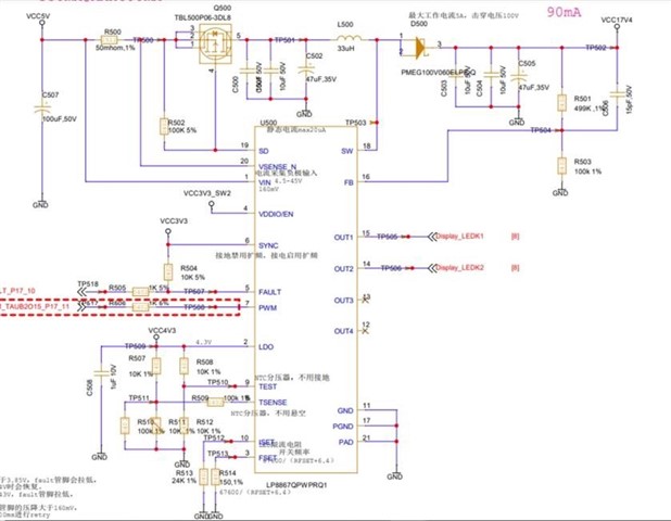
My customer is using LP8867-Q1 for their project and they want us to help them to review the schematic, and they have a problem about the configuration of VDDIO so I'm looking for your help.
I have attached the schematic diagram below, and their application scenario is that the input voltage is 5V, the output voltage is 17.4V, and the driving load is a display string light, and the working current is about 90mA. Also, they see a description in the datasheet that says "If LED fault is detected, the device continues normal operation and only the faulty string is disabled. The fault is indicated via the FAULT pin which can be released by toggling VDDIO/EN pin low for a short period of 2 µs to 20 µs. LEDs are turned off for this period but the device stays in NORMAL state. If VDDIO/EN is low longer, the device goes to STANDBY and restarts when EN goes high again. This means if the system doesn't want to simply disable the device because of LED faults. It could clear the LED faults by toggling VDDIO/EN pin low for a short period of 2 µs to 20 µs. "
So they want to know if they need to do a controllable pull-up of the VDDIO pin, or do a directive pull-up, and if the SYNC and FAULT pins are the same as the VDDIO pull-ups, and how they should be configured if they don't need to be configured that way.
Thank you very much for your assistance!
Best regards,
Shawn Li

