This thread has been locked.

If you have a related question, please click the "Ask a related question" button in the top right corner. The newly created question will be automatically linked to this question.

TPS25750: TPS25750S ext. MOSFET

Part Number: TPS25750

Dear TI,

we are currently using the TPS25750S with 2x SSM6K513NU MOSFETs for the external power path. Unfortunately the MOSFETs are not switched by the TPS.

Currently we use the TPS in dead battery mode so VIN_3V3 and PP5V are not available and the TPS is supplied by VBUS. The LDO (1V5; 3V3) are. The TPS uses the EEPROM to load the configuration and negotiates the PD contract with the power adapter. In our case max. 45 W 15 V 3 A. We are using the ADC Config: ADCIN1 = 7 (tied to LDO_3V3) and ADCIN2 = 5 (LDO_3V3 / 2). Here are our voltages when we connect the device to a our 5 V USB Hub:

VBUS = 5 V

GATE_VBUS = 5 V

GATE_VSYS = 1.6 V

DRAIN = 0.64 V

VSYS = 1.6 V

VIN_3V3 = 0 V

PP5V = 0 V

Do you have any advice why the TPS does not switch the MOSFETs?

The register map look fine to me and the register 0x26 displays: PP3switch enabled (system input) / PP1switch disabled

Here is a snip of the schematic of the device. (VBUS_SW = V_SYS)

Best regards,

Tom

  • Hi Tom,

    Can you share the .json file you used to generate the I2C EEPROM image using the gui?

    Can you check the status registers to see:

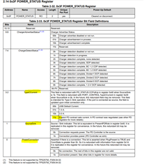
    If a connection is valid and what type of connection it is (Power_Status 0x3F)

    Can you also check the Boot_Status register to confirm the configuration has been loaded from the EEPROM?

    Thanks and Regards,

    Chris

  • Hi Chris,

    i attached the TPS-JSON Config below.

    This is the Power Status Register. Our device is connected to a normal USB-Hub without PD capabilities.

    {
      "questionnaire": {
        "device": "TPS25750",
        "answers": [
          null,
          3,
          0,
          2,
          1,
          1,
          3,
          0,
          1,
          1,
          null,
          0,
          0,
          0,
          0
        ],
        "vendorId": "0000",
        "productId": "0000",
        "version": "1.0.0.2"
      }
    }

    Thank you & best regards,

    Tom

  • Hi Tom,

    Do you have a PD analyzer or CC line decoder? If yes, could you share a PD log when you attach a source to the port?

    The json seems to be fine and it looks like you are booting properly from the EEPROM. 

    The TypeC current is telling us that a PD contract is not being negotiated, and you are in a type-C current, but it does not explain why the Sink power path is not turning on.

    Which version of the GUI are you using to generate the .json and .bin?

    If you corrupt(erase) or remove the EEPROM so you only boot in dead battery mode and never load the image, do you see the FETs assert? This will tell us if it is a hardware or .json issue.

    Thanks and Regards,

    Chris

  • Hi Chris,

    sorry for the delayed response. We do not have a PD analyzer or CC line decoder.

    We are using the version of the GUI - 0.6.0

    If we start the application with an empty EEPROM, the MOSFETs are not switched either.

    We currently think that it could be a hardware problem with the MOSFETs because the MOSFET behave strangely. We have ordered new MOSFETs and will install them manually and keep you informed.

    Thank you very much for the support & best regards,

    Tom

  • Hi Tom,

    Sounds good, please keep me updated.

    While you are waiting, it may also be worth trying to remove the mosfets completely and seeing if the gate drive signals assert (with no mosfets on).

    Thanks and Regards,

    Chris

  • Hi Chris,

    good news. We manually placed new SSM6K513NU MOSFETs on the PCB and the TPS is working now.

    Thank you for the fast support! :)

    Best regards,

    Tom