
- Ask a related questionWhat is a related question?A related question is a question created from another question. When the related question is created, it will be automatically linked to the original question.
I'm using the TPS65073 to control the backlight consisting of a string of 4 LEDs.
I can always turn the LEDs on (via setting register 0x18 to 0x90), as well as adjust the PWM duty cycle from 0 to 100% (via setting register 0x19 to 0x00 -- 0x63).
If I turn the backlight off (via setting register 0x18 to 0x10), then most, but not all, the time the backlight fails to turn back on. When failing, the boost converter still works -- going to ~12 V. However, the Isink pins fail to sink any current. Once failed, only a power cycle will bring it back to life.
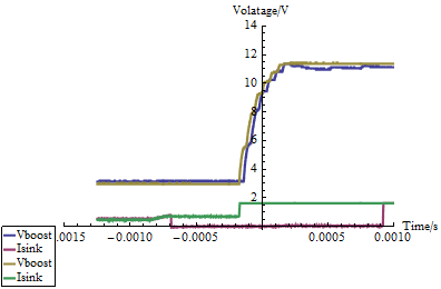
The figure below is an example of the working and non-working condition. Vboost is the voltage at the FB_wLED pin. Isink is the voltage at the Isink1/Isink2 pins (they are tied together). The blue/red pair shows proper operation. The boost voltage comes up, Isink goes low to sink the current. At ~0.8 ms, Isink goes "high" to start the first PWM cycle. The gold/green pair shows the failure. The boost voltage comes up, but Isink fails to go low. At its voltage and the i-v characteristic of the LED string, less than 1 uA flows through the LEDs.
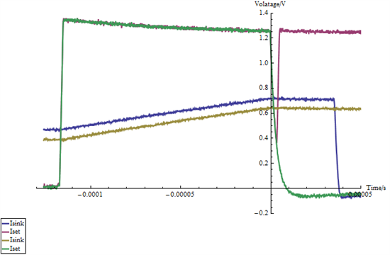
The voltage at Iset2 does something different between the failing and success cases as well, as shown below. In the success case (blue/red), Isink drives low, similar to the plot above. There is a ~4 us glitch in Iset, but apparently it has no effect. In the failure case, (green/gold), Isink does not go low and Iset does not recover from the glitch.
The circuitry is the same as my earlier postings:
backlight circuit values: iset2 = 124 kohm, L4 = 33 uH.
power source either battery, AC, or USB.
Any suggestions would be most appreciated!


