This thread has been locked.

If you have a related question, please click the "Ask a related question" button in the top right corner. The newly created question will be automatically linked to this question.

BQ25798: BQ25798

Part Number: BQ25798
Other Parts Discussed in Thread: BQSTUDIO, BQ40Z50

Tool/software:

Hello, any help with the following would be greatly appreciated.

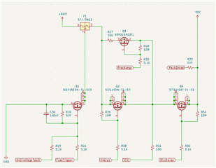
We are seeing odd behaviour with the BQ25798 when charing a 2s0p battery pack and struggling to determine the fault, perhaps configuration but as of yet, the root cause eludes us.

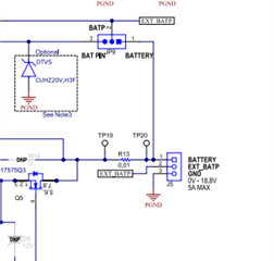
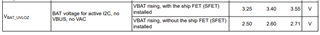
When we have the battery pack installed the 0x1d VBAT Present status register correctly detects the pack, however, after supplying a voltage to the AC1, AC2, and VBUS lines we see the status register flip to VBAT NOT Present.  We believe this is stopping the device from charging the battery pack.

BQStudio BQ25798 Field View

  • Battery Installed w/ no supply on VAC1, VAC2, VBUS
    • VBAT Present Status (0x1D) = VBAT Present
    • AC1, AC2, VBUS Status (0x1B) = NOT Present
  • Battery Installed w/ supply (8.4v 0.5a) on VAC1, VAC2, VBUS
    • VBAT Present Status (0x1D) = VBAT NOT Present
    • AC1, AC2, VBUS status (0x1B) = Present

This was discovered during a pack learning cycle with the BQ40Z50-R3 gauge, everything works fine until we attempt to recharge the cell after a discharge cycle.

[BQ25798] -> [BQ40Z50] -> Cell 1 + 2.

Registers

* Created: Thu Jul 25 04:59:05 AEST 2024
*
* Format: Register Name  tab Character,\t  Register Address  tab Character,\t  Hexadecimal register value.
* BQZ Container: Charger_2_00-bq25798.bqz
*
REG00	00	12
REG01	01	348
REG03	03	C8
REG05	05	24
REG06	06	12C
REG08	08	C3
REG09	09	05
REG0A	0A	63
REG0B	0B	DC
REG0D	0D	4B
REG0E	0E	3D
REG0F	0F	A2
REG10	10	85
REG11	11	40
REG12	12	00
REG13	13	21
REG14	14	16
REG15	15	AA
REG16	16	C0
REG17	17	7A
REG18	18	54
REG19	19	12C
REG1B	1B	2F
REG1C	1C	0A
REG1D	1D	00
REG1E	1E	00
REG1F	1F	10
REG20	20	00
REG21	21	00
REG22	22	0F
REG23	23	12
REG24	24	40
REG25	25	10
REG26	26	00
REG27	27	00
REG28	28	00
REG29	29	00
REG2A	2A	00
REG2B	2B	00
REG2C	2C	00
REG2D	2D	00
REG2E	2E	30
REG2F	2F	00
REG30	30	00
REG31	31	00
REG33	33	00
REG35	35	00
REG37	37	00
REG37	39	00
REG3B	3B	00
REG3D	3D	00
REG3F	3F	00
REG41	41	00
REG43	43	00
REG45	45	00
REG47	47	00
REG48	48	18

  • Hi Ben,

    After discharge, what is the voltage at the charger's BATP pin?

    Regards,

    Jeff

  • As per the INR18650-29E datasheet the Discharge Cut-off Voltage is 2.50v * cell count (2) = 5.0v. The BQ25798 BATP pin is connected directly to the pack+ pin (+BAT below), avoiding the BQ40Z50 CHG/DSG FETs. VDC below connects to the BQ25798 BAT pins.

    Note: The symptom persists even with a fully charged pack (8.4v).

  • Hi Ben,

    The CHG and DSG FETs are in series with the top cell.  BATP should connect to protector input, which is input side of CHG FET.  If you connect to a simulated battery with BQ40Z50, does the charger function correctly?

    Regards,

    Jeff

  • Hi Jeff,

    We've connected a power source directly to the DSG FET, going around the BQ25798, and attached a DL3021A to simulate the battery with no issue; we see current sink.  This test was also performed with real cells; again, no problems were encountered.

    Testing with BQ25798 in the loop results in no current sink, BATFET remains disabled.

    Reading sections 8.3.3 and 8.3.4 of the datasheet we performed several test scenarios.

    Scenario: Device Power Up from Input Source without battery cells

    Fault Interrupt Flags:  All clear.

    VBAT Present Status: VBAT Not Present

    AC1/AC2/VBUS Present Status: Present.

    VSYS Status: NOT in VSYSMIN Regulation.

    SYS: 0v (no matter the fiddling, we never saw a supply)

    Scenario: Device Power Up from Input Source with battery cells

    Fault Interrupt Flags:  All clear.

    VBAT Present Status: VBAT Present.

    AC1/AC2/VBUS Present Status: Present.

    VSYS Status: NOT in VSYSMIN Regulation.

    SYS: 8v

    Scenario: Device Power Up from Battery without Input Source

    Fault Interrupt Flags:  All clear.

    VBAT Present Status: VBAT Present.

    AC1/AC2/VBUS Present Status: Not Present.

    VSYS Status: NOT in VSYSMIN Regulation.

    SYS: 8v

    One thing that stands out during the testing is the immutable nature of the VSYS Status register (1Eh), the datasheet clearly states:

    0h = Not in VSYSMIN regulation (VBAT > VSYSMIN)
    1h = In VSYSMIN regulation (VBAT < VSYSMIN)

    Yet, regardless of VBAT or VSYSMIN, we see no change from Not in VSYSMIN regulation.

    We have several BQ40Z50EVM-561 evaluation modules lying around, can you suggest which pin we'd connect the BAT and BATP of the BQ25798 on this EVM?

    Pack+ results in the same issues as we see on our custom board. 

  • Hi Ben,

    The EVM default jumper JP9 pin1=pin2 connects BATP to the battery terminal side of the shipFET.  So you should be able to connect PACK+ to J5 pin1 and PACK- to J5 pin3.

    Regards,

    Jeff 

  • When the BQ40Z50 disables the DSG FET the BQ25798 no longer detects a battery pack.  Charging never occurs.

  • Hi Ben,

    DSG only turns off to prevent undervoltage so cell voltage is is low, correct?  With CHG FET on, charger should be able to trickle charge with 100mA through the DSG FET body diode until the cells exceed the protector undervoltage treshold.  Is 100mA of current flowing out of the BAT pin?  Note that the charger ADC does not report this 100mA.  When the shipFET is installed, the charger needs to see up to 3.55V at BATP in order to start charge.

    If you short the charger's shipFET, what happens?

    Regards,
    Jeff