This thread has been locked.

If you have a related question, please click the "Ask a related question" button in the top right corner. The newly created question will be automatically linked to this question.

TPS61391: APD

Part Number: TPS61391

Tool/software:

We are trying to improve a design with the requirement of creating a high-voltage source (50V) from a lipo-battery (Vin 3 to 5V), with the possibility of sourcing up to 10mA from the high-voltage source.

The current design is based on an LT8570 in boost configuration with a very large inductor, operating in a low-efficiency area.

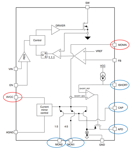
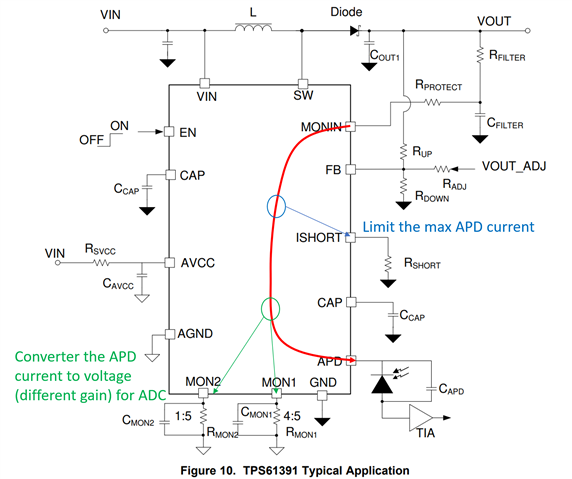
I'm looking for some alternative solutions that are more efficient and with a smaller footprint. I stumbled on the TPS61391, which may be a reasonable choice, but it comes with extra features (APD and current mirrors), which (I assume) we would not need. I also do not really understand what is the purpose of the APD and if it's necessary since it's referenced in the application 

  • Can somebody help me understand if this part is adequate for our use case? I'm also looking for alternative solutions (charge pumps maybe?), any suggestion is appreciated!
  • What's the point of the APD? Can the converter be used without it?

Thank you!

  • Hi Andrea,

    The part of current mirror and monitoring is designed for applications that the APD current should be monitored.

    In your application, the current mirror and monitoring part is not needed. You can totally disable this part as below:

    • Connect the two pins in red circles to GND;
    • Leave the five pins in blue circles floating.

    With so, TPS61391 can be configured as a normal boost converter.

    If possible, could you share what's your application? Thank you.

    Regards

    Lei

  • Thank you. The application is transcutaneous electrical stimulation.

    I still have some confusion about the APD and monitor functionalities. In fact, it would be useful for us to integrate the current limit and current monitor at the output, so if these functionalities are possible directly with the TPS61391 it would be great.

    1. Could you elaborate on the APD? I do not understand how this limits the current. What external components are required there?
    2. Is the output short-circuit current limit (set with R_short) independent or does it only work with APD?
  • Hi Andrea,

    Following is the typical application for your reference.

    Could you elaborate on the APD? I do not understand how this limits the current. What external components are required there?

    The APD voltage is close to the VOUT. The current flows from VOUT --> MOMIN --> Internal circuit --> APD --> load is monitored and limited. The max current is set by one resistor only on the ISHORT pin.

    Is the output short-circuit current limit (set with R_short) independent or does it only work with APD?

    Only the current flows from VOUT --> MOMIN --> Internal circuit --> APD --> load is limited by the R_short.

    If you don't use the part of current mirror and monitoring, the max current flows from VOUT --> load is decided by the normal peak switching current, and there is no VOUT short protection.

    Regards

    Lei

  • Thank you, I think I understand now.

    I still have one concern on the design though.

    In section 8.2.2 a sample application is shown, with parameters similar to my use case.
    It seems to me that Lmax and Lmin are calculated with typical values, should they not be calculated with max/min values from the datasheet?
    For example, Lmax uses 0.8A of I_lim and 600kHz of switching frequency. If instead we use 800kHz and 1.2A we reduce a lot the final Lmax value, thus shrinking the margin for L

    In my application, this makes the difference between feasible and not feasible with this IC, as I have
    - Vin = from 3V to 5.5V
    - Vout = 50V
    - Iout from 0mA to 10mA max

  • Hi Andrea,

    For example, Lmax uses 0.8A of I_lim and 600kHz of switching frequency. If instead we use 800kHz and 1.2A we reduce a lot the final Lmax value, thus shrinking the margin for L

    Your understanding is correct. The more strictly calculated Lmax should be smaller.

    Well, in your application, you can simply select a 4.7μH inductor, for the following three reasons.

    1.  We have verified applications that are very close to yours, of which the inductor is 4.7μH;
    2. Most of the units has the "typical" values, so actually Lmax can be calculated with typical values. Lmax is not a mandatory restriction. 
    3. If the inductor is too small, there will be concerns on the max Iout.

    Regards

    Lei