Other Parts Discussed in Thread: TIDA-010074
Tool/software:
Hi TI team,
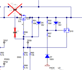
Going through the design files for the BQ76952EVM, I could see that an N-channel MOSFET is used in the FETs connection page for the discharge MOSFETs. Upon researching the circuit diagram, I came to know that it is for the for reverse polarity protection while a charger is connected on. Need to know the exact working and is there any other way to implement the protection?
Attached the image for reference.

What is the working of Q10 in case of charger reverse polarity? while researching, found similar circuit in the reference design TIDA-010074.
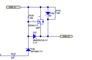
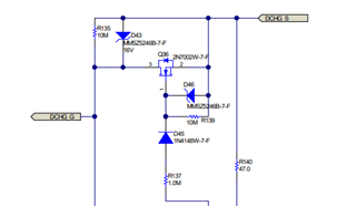
The circuit used in the TIDA-010074 is same as the one here, but it includes another circuit for the charge MOSFETs. The circuit involving Charge MOSFETs is using P-Channel MOSFETs.What is the working of that circuit?
For reference,

Thanks,
Naveenkrishna V

