Other Parts Discussed in Thread: BQ41Z50, BQSTUDIO, EV2400
Tool/software:
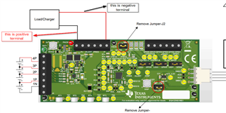
I am using SLUUD32 BQ41Z50 Li-Ion Battery Pack Manager Evaluation Module Section 2.3 EVM Connections as a reference.
Bottom of page 3 / Top of page 4 describes connecting the cells, along with Figure 2-1.
Per page 4 I started hooking in the individual cells beginning with 1N, 1P, then adding 2P, 3P.
Things seemed OK at this point.
When I attempted the 4P hookup, the board immediately got very hot.
This happened with a 4th cell, and also if I instead tried to "place a short across unused voltage sense inputs" (page 4).
1. What am I missing here? The cell hookup was the first step given in Section 2.3... should some other step have come first?
For example, is it required to connect Batt+ / Batt- first, and then hook up the cell balancing wires?
2. Figure 2-2 on page 4 is titled "J1 and J5 Terminal Block Connections" but it seems to be describing J4 instead.
Please clarify (is the table titled wrong?)
3. Should I be able to communicate with the BQ41Z50 from BQStudio (using an EV2400) even if no battery or power connections are made to the board?
To ask it another way, can the BQ41Z50 get power from connector J3 (which goes to EV2400 PORT 1 SMB)?