This thread has been locked.

If you have a related question, please click the "Ask a related question" button in the top right corner. The newly created question will be automatically linked to this question.

LM3410: Minimum PWM Duty Cycle too high?

Part Number: LM3410

Tool/software:

Hi,

I've built a LED Driver Circuit using the LM3410 in the 1,6mhz version.

I'm driving 4 Leds with 2,8vf at 350ma.

My schematic is based on the Example 8.2.5 in the Datasheet.

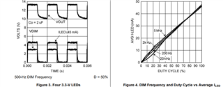
I'm using a 16khz PWM Signal, but the LEDS start to light up with a duty cycle greater than 30 percent.

Reducing PWM Frequency helps a bit, but even at very low frequencies it doesnt seem to work properly.

At 1khz the leds turn on at 5% duty cycle.

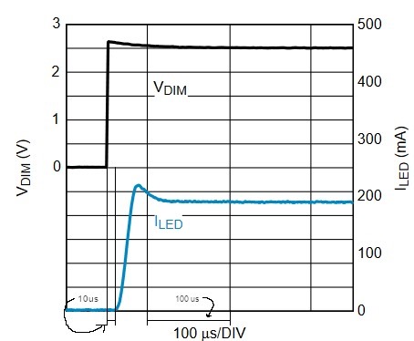
Is this normal behaviour and related to the 20millisecond startup time?

Am i right, that the LM3410 regulates the output current instead of keeping it constant and applying the pwm signal to shut the led's on and off?

I need a high PWM Frequency, since the product is intended for film set lighting.

If there is a better option that takes Li-ion input voltage and works for 3 to 4 pieces of 1watt LED's, I'd also be interested to hear about that.

Thanks,

Markus Harthum

  • Hi, Markus, 

    Do you have test waveform to clarify your question? 

    Do you mean that when using a 16khz PWM Signal, the LEDS can't be lit up with a duty cycle < 30 percent. Does it happen with first duty cycle or it happens every cycle? It should take longer time to charge output capacitor for first cycle. While LED should be able to turn on with small duty cycle. 

  • Hi,

    thanks for your reply.

    i dont have a waveform yet, i wont be near the pcb for the next 2 weeks unfortunately.

    But the leds dont turn on at all, not just for the first few cycles.

    I know the Figure 4 chart, thats why i chose the lm3410. But good to know that it should work, then i will investigate further. 

    thanks a lot,

    Markus

  • A very nice colleague just sent me a snapshot from the waveform!

    For test purposes, there is a 1khz, 3% duty cycle square wave pwm signal on DIM,

    And the signal measured is the voltage at the Feedback pin.

    The voltage only starts 15us after the pwm signal. For a 16khz signal, that would be the reason why low duty cycles dont work.

  • Can you/your colleague help capture more channels in the figure? 

    1. DIMM/FB/SW/IN

    2. DIMM/SW/IN/VOUT(C2+) 

    Have you tried dimming after VOUT set up (For example, dimming from 100%  down to 3%) and if there is any difference? 

    I'm afraid there is not enough energy to charge up output capacitor with small duty cycle starting from powering up. 

    I will apply for EVM board to test while it might take one week to get the board. 

  • Hi,

    i will take me some time to get the captures, but i'll post them as soon as possible.

    I have tried dimming down, same problem, no difference.

    But i have learned a lot about PCB design in the past few days, and i think i might have much too long ground loop from the output capacitor to the LM3410 Gnd pin.

    In the Layout Guidelines in the Datasheet it clearly states:

    The most important consideration when completing a boost converter layout is the close coupling of the GND connections of the COUT capacitor and the PGND pin. The GND ends must be close to one another and be connected to the GND plane with at least two vias.

    My COUT GND is very badly coupled, there is a huge GND Loop to the IC.

    I've attached a screenshot of the Layout, including the return path for GND. But I'll try to solder a wire from COUT directly to Pin6, and see if that changes something.

    (Also the routing of the DIM1 Signal on the Bottom Layer is really bad.)

  • You may try that, while I'm afraid that small PWM duty cycle with high DIM frequency like16kHz won't be able to slew up/down output capacitor so fast. Smaller capacitor may helps while it will cause stability and ripple issue. 

    Or, you could maybe try an NFET on the low side of Cout to disconnect the capacitor during the off time so that it doesn't discharge very far.

    There is another post about that fyi in below link 

    (+) LM3410-Q1: pwm dimming - Power management forum - Power management - TI E2E support forums

  • Thanks for the link.

    I'm currently also working on a circuit with a boost Converter to Step up Voltage to the Series Voltage of the LED's, and then use linear drivers to pwm them. Maybe this works better.

  • My colleague found out something interesting in the meantime.

    In the Datasheet to the 190ma Evaluationboard (https://www.ti.com/lit/ug/snva410a/snva410a.pdf?ts=1723208324961&ref_url=https%253A%252F%252Fwww.ti.com%252Ftool%252FLM3410XBSTOVPEV)

    on Page 4, Figure6 is a Chart of the Current to the LED VS the Voltage at the DIM Pin.

    There is around 10us delay between the Dim Signal going high and the current through the LEDs.

    He found the same delay, when measuring the voltage at the node between Inductor Out and Diode In. So even before the Capacitor comes into play, we're already lagging behind! And even stranger, the delay gets worse with increasing Input Voltage. See attached two screenshots, one with 2.7V VIN and the other with 5.5V VIN.

  • Hi Markus,

    The yellow line means SW point, and the orange line means Vdim, is it correct? Could you also put the ILED and Vfb in this picture? That would be very helpful. Thanks!