Other Parts Discussed in Thread: TPS25983
Tool/software:
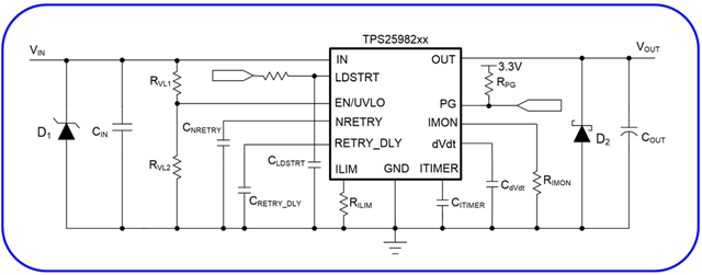
I was testing this part(TPS259822ONRGE) for its current limit but unable to draw load more than 6A, I need to check for its maximum current limit. Please help on this circuit.
This thread has been locked.
If you have a related question, please click the "Ask a related question" button in the top right corner. The newly created question will be automatically linked to this question.
Hi Rahul,
Please share the schematic or BOM values so that I can understand the ILIM value. Also kindly share the setup details like load, vin.
Best Regards,
Arush
Hi Arush,
Please refer the below schematic and BOM. I got these values from the design calculator available on TI design calculation file and I am using the same. I am using Vin=3.3V and using a resistive load of 0.22R. Please have a look on it and suggest necessary changes.
| RVL1 = | 1000 | kOhm |
| RVL2 = | 845 | kOhm |
| RILIM = | 84.5 | Ohm |
| RIMON = | 412 | Ohm |
| RPG = | 10 | kOhm |
| CdVdt = | 33 | nF |
| CITIMER = | 4.30 | nF |
| CRETRY_DLY = | 2.20 | nF |
| CNRETRY = | 470 | nF |
| CLDSTRT = | 100 | nF |
| CIN = | 0.01 | uF |
| COUT = | Optional | |
| D1 = | SMCJxx | |
| D2 = | B530C-13-F |
Thanks & Regards
Rahul
Hi Rahul,
Are you using EVM or your own board. Do you have any waveforms? Are you using long wires. What is voltage at device Vin when current is increasing (wire drop at vin shouldn't trigger device UVP).
What is happening above 6A current. Is device shutting down?
Best Regards,
Arush
Hi Arush,
I am using my own board, I have not captured any waveform but if you need I can capture and send. I am not using long wires also. Since I am using Variable DC power supply, input voltage which is 3.3V is not dropping.
When I am applying more than 6A the device is getting restarted again and again and also it is starting to produce some sound.
Regards
Rahul
Hi Rahul,
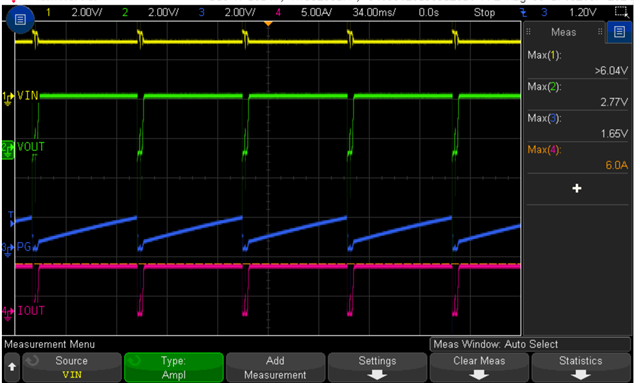
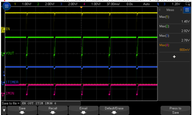
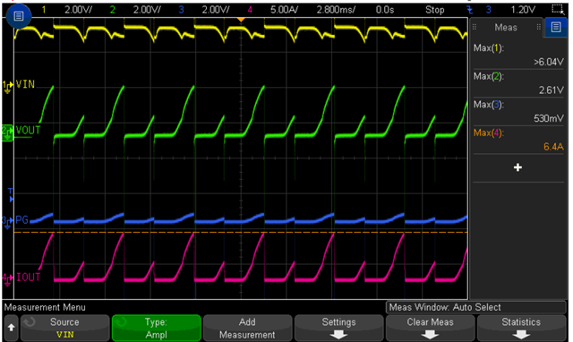
Yes, waveforms can help. Please probe near the deice pins or test points you have. Probe vin, vout, PG, dvdt, en, itimer, imon. You can send multiple captures.
Can you test with higher Vin like 5V or 12V. This will remove UVP as suspected issue. Please change load accordingly. increase current drawn gradually.
Sound shouldn't come. If it is sparking sound, then please check all the connections. Is there any physical damage to the device.
Best Regards,
Arush
Hi Arush,
I will share the waveforms in a while.
The device can not be operated above 3.6V as its Vin is 3.3V. So the operating voltage is not an issue. Beyond 3.6 it is going for OVP.
As far as sound is concerned, it is not sparking sound, it is coming from the device on load greater than 6A. Device is not damaged it is working fine.
Regards
Rahul
Hi Rahul,
Yes, you are correct, earlier I did not check the variant of the device.
I will share the waveforms in a while.
Sure.
As far as sound is concerned, it is not sparking sound, it is coming from the device on load greater than 6A. Device is not damaged it is working fine.
This should not happen as there are no moving parts. Please check the connections once just in case. Also, I will ignore this for now and will focus more on finding the root cause using waveforms.
Best Regards,
Arush
Hi Arush,
Please find some of the waveforms which you have asked. Let me know if you have any query, We can have a teams call or even you can reach me on my number-9810821638.
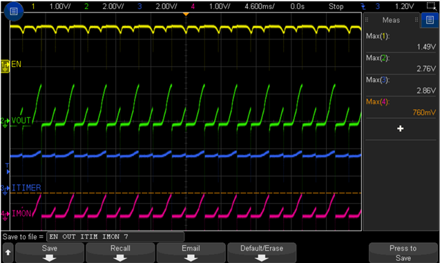
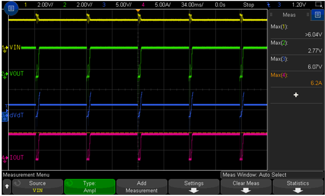
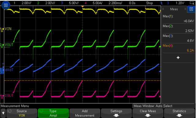
Regards
Rahul
Hi Rahul,
I think I missed something last time when I was look into this. I think you are not pulling LDSTRT to GND. you mentioned 100nF cap at LDSTRT. If you are not using that signal, please pull it down to GND.
Best Regards,
Arush
Hi Arush,
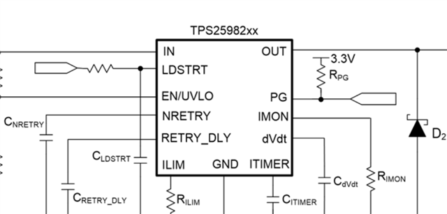
I have tried pulling down LDSTRT to GND directly as well as with 10K resistance, but it still not taking load more than 6A. Now I have a doubt in schematic that whether we need to connect LDSTRT and PG with resistor in between or not, if yes then what will be the value of the resistor?
Also if any changes require in schematic to increase the current capacity, please suggest.
Regards
Rahul
Hi Rahul,
PG needs to be pulled up as it is an open drain pin. LDSTRT if not required should be short to GND. It is a handshake signal.
It looks like the issue is in startup. Can you please try without any load and then after startup, place the load.
Another option is remove Cout and open the dvdt pin.
Please inform me if this answers your issue.
Best Regards,
Arush
Hi Arush,
I have tried this but still it is not working, also I am starting it without load and connecting the load after startup.
Regards
Rahul
Hi Rahul,
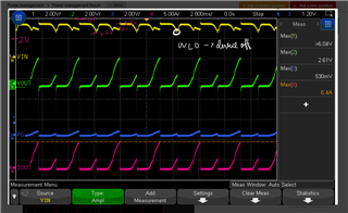
Is device going into UVLO due to high voltage drop at wire? You can force 1.5V external voltage at the En pin to verify this.
Best Regards,
Arush
Hi Arush,
I have already tried this but it is also not working, even I have tried to maintain the input as well as enable voltage constant even on load, but that also did not work. Also I have minimized the wire length to reduce the voltage drop. Please try to find the error once by going through the circuit and waveforms again.
Meanwhile Can you please confirm on the below points:
Regards
Rahul
Hi Rahul,
1. It is recommended to use the device up to 24V Vin max voltage. This device has a overvoltage protection feature so if the Vin is above 3.7V, it turns off the main switch. The minimum voltage required at input to keep the device logic on is 2.7V.
2. No, this is 2O variant with OVP of 3.7V. If you want to test the device at higher voltage like 12V, you should use 4O or 7O variants which won't by default perform OVP at 12V.
3. The input voltage is valid for all the parts in series. The by default OVP may block the Vout depending on the variant and voltage level. So variants should be selected based on application. If OVP is not required, then 7O or 7L should be used.
4. If the end application requires continuous 12V, then use (4/7)(O/L) variants. For 24V, use 7(O/L) variants. I would also suggest since 24V is very near the max recommended range, TPS25983 can be used which have 26V as max recommended range and provides programmable OVP threshold.
Best Regards,
Arush