This thread has been locked.

If you have a related question, please click the "Ask a related question" button in the top right corner. The newly created question will be automatically linked to this question.

TPS65219: 3.3V no output

Part Number: TPS65219

Tool/software:

Dear team, 

There is issue on TPS6521901 3.3V output. 

For some reason, if the customer input 5V to PMIC while the residual voltage of 50mV is on the 3.3V line, the 3.3v output don't turn on. Not even re-trying. 

At datasheet, we can see below specification. Though the residual voltage of 50mV is below 220mV, Why Buck2 of TPS6521901 do not turn on? please let me know your opinion. 

Thank you. 

  • Hi,

    Thanks for reaching out. Could you share the PMIC schematic in a searchable PDF and a power-up capture showing VSYS, enable pin, Buck and LDO output voltages? Please use a small time scale (~4ms) and fit as many channels as possible in the same capture.

    Thanks,

    Brenda

  • Hello Brenda, 

    I will share schematic and waveform soon, Quick question.

    Is there any way to ignore below specification like register configuration?? 

    Thank you. 

  • Hi,

    The TPS65219 PMIC executes two residual voltage checks; the first one occurs before the power-up sequence is executed and a second occurs during the power-up sequence (right before each rail is turned ON).

    The first check can be disabled by changing register field "Register field "BYPASS_RAILS_DISCHA RGED_CHECK" but the second one cannot be disabled. Please note that changing any register field would require to turn-ON the PMIC first and get the device in Active state to enable I2C communication. 

    Thanks,

    Brenda

  • Hello Brenda, 

    we found out where the residual voltage is coming from. This is come from E-PHY 

    - Residual voltage VLDO4 , 2.5V line : 4~500mV /  VDDIO, 3.3V line : 50mV. 

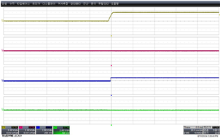
    Above condition, Although 5V VCC input to PMIC, Is it normal that the first output, Buck2, isn't turned on at all like below? 

    - Yellow : VSYS, 5V / Red : Buck2 out, 3.3V / Blue : VDD1P8(Pin14) / Green : GPO1

    Buck2 output , It does not turn on at all.

    Thank you.  

  • Hi,

    Thanks for sharing an update. If the backfeeding issue on VLDO4 exist before the PMIC executes the power-up sequence, then none of the rails will turn-ON. The reason is because as I mentioned in my previous message, the PMIC performs the first residual voltage check before executing the power-up sequence.  

    Do you see a voltage on VLDO4 before Buck2 is turned ON?

    Thanks,

    Brenda

  • Hi Brenda, 

    As mentioned before, we see a residual voltage on VLDO4(0.4~0.5V) , Buck2(0.05V) before Buck2 is turned ON. 

    That's why I ask a way to ignore residual voltage checks. but There is no way to configure PMIC internal register. 

    I think this is no PMIC issue.  

    Thank you for your great support. 

  • Thank You! Once the backfeeding issue on VLDO4 is resolved, feel free to let us know if there are any issues with the PMIC. 

    Thanks,

    Brenda