Tool/software:
The H, HB, and HC families of high-side power switch devices implement current limit by the placement of a resistor (RILIM) in external circuitry connected to the chip, and the current limit can be adjusted by the value of the resistance used. This feature is discussed further in this app note.
Current limiting may occur above or below the current limit setting however, based on several factors. Knowing the range where current limiting may occur, then, is vital to device users. The inherent current limit accuracy for each device can differ at different levels of current. For example, at lower current limit settings, a device's current limit accuracy may be +/- 20% (current limiting could activate at as low as 20% less or as high as 20% more than the intended current limit value), while at a higher current limit setting the accuracy would be +/- 3%. Additionally, the tolerance of the RILIM resistor being used will influence this range where current limiting may activate.
These sources of variability make estimating the effective range of current limit less straightforward, so we designed a calculator that takes all of these variables into account here:
H_HB_HC_ICLPDISS_calculator.xlsm
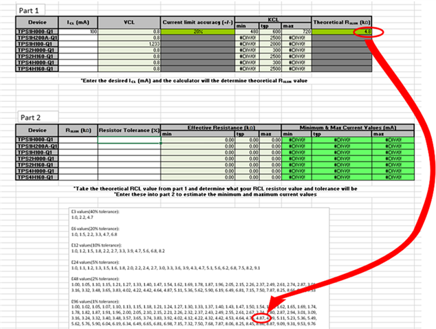
As an example, we'll use the calculator to estimate the expected current limit range for TPS1HC30. The user would begin by entering their desired current limit as the input to part 1, in this case 100 mA.

The output of significance to the user is the Theoretical RILIM. We call it theoretical because this value might not have an exact match among standard resistor values.
There is a list of standard resistor values and their associated tolerances toward the bottom of the sheet. The user can review this and choose a value that they know they'll have access to and/or plan on using.

The standard resistor value and its tolerance are then entered part 2 of the calculator. The calculator presents the estimated effective range of the current limit as the output. Effective resistance represents the minimum, typical (or nominal) and maximum resistance of RILIM given its tolerance:
REFF,ILIM,MIN = RILIM * (1-tolerance%)
REFF,ILIM = RILIM
REFF,ILIM,MIN = RILIM * (1+tolerance%)
Minimum, typical, and maximum current limit are calculated as follows:
ICL,MIN = (REFF,ILIM,MAX * VCL) / KCL,MIN
ICL,TYP = (RILIM * VCL) / KCL,TYP
ICL,MAX = (REFF,ILIM,MIN * VCL) / KCL,MAX

The HC device calculator works in a similar fashion, with the steps shown here.


Users may also want to know if thermal shutdown is a risk at their device's operating conditions. The thermal junction calculator can answer this question simply (disclaimer: at the time of writing, the thermal junction calculator can only calculate TJ for a single channel on each device).
As an example, we'll use the calculator to estimate the expected TJ for TPS1HC30. The user only has to enter IOUT and the ambient temperature (TA) as inputs.

We can see that the cell showing TJ is still green, indicating that the device is not at a temperature where thermal shutdown may occur.

When the inputs result in a TJ where thermal shutdown may occur, the cell showing TJ will turn red. The corresponding calculator for the H family of devices works in an identical fashion.
-Nate Newman

