Tool/software:
测试UC1875时,发现输出采样回4脚的各种电压,只要比3脚电压高的话,误差放大器输出恒定高电平,移相角也是恒定的。此时似乎输出电压是不受移相角所控制的(常规的是通过移相角去控制输出电压的)。
貌似只有平衡时,才构成整个回路的闭环。
那么,怎么通过移相角去控制输出电压呢?即移相角大点输出就大点,移相角小点输出就小点
This thread has been locked.
If you have a related question, please click the "Ask a related question" button in the top right corner. The newly created question will be automatically linked to this question.
Tool/software:
测试UC1875时,发现输出采样回4脚的各种电压,只要比3脚电压高的话,误差放大器输出恒定高电平,移相角也是恒定的。此时似乎输出电压是不受移相角所控制的(常规的是通过移相角去控制输出电压的)。
貌似只有平衡时,才构成整个回路的闭环。
那么,怎么通过移相角去控制输出电压呢?即移相角大点输出就大点,移相角小点输出就小点
When testing UC1875, it was found that for various voltages sampled back to pin 4, as long as the voltage is higher than pin 3, the error amplifier outputs a constant high level and the phase shift angle is also constant. At this point, it seems that the output voltage is not controlled by the phase shift angle (the conventional way is to control the output voltage through the phase shift angle).
It seems that only when there is balance, does it form a closed loop for the entire circuit.
So, how to control the output voltage through phase shift angle? The larger the phase shift angle, the larger the output; the smaller the phase shift angle, the smaller the output
Hello,
When QA and QD are on at the same time and FETs QB and QC are on at the same time energy will be transfered primary to secondary. QC and QD are phase shifted to control duty cycle.
When QA and QD are in phase there will be 100% duty cycle.
When QB and QC are in phase there will be 100% duty cycle.
When QA and QD are 180 degrees out phase there will be 0% duty cycle.
When QB and QC are 180 degrees out phase there will be 0% duty cycle.
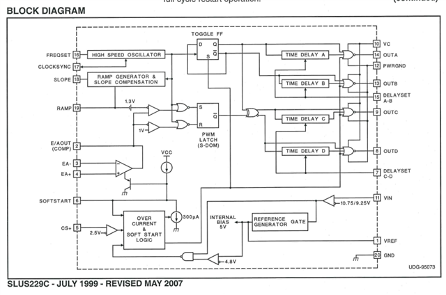
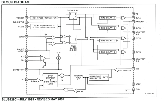
Pin 4 is EA+ and Pin 3 is EA -. These pins should be controlled to the same voltage. The voltage amplifier output pin 2 is actually what controls the duty cycle.

If you want to test the UC1875 open loop I would set the error amplifier as a voltage follower. You tie EA- to E/A out and control EA+ with a bias supply. Then by adjusting EA+ voltage you can adjust the duty cycle and phase shift.
Thank you for interest in Texas Instruments (TI) products. If you have a related question, please click the "Ask a related question" button in the top right corner. The newly created question will be automatically linked to this question.
Regards,
We have tested and found that there are only two states for the phase shift angle, which are determined by pin 2 of the error amplifier: when balanced, 0.24V corresponds to QA and QD are in phase, and the maximum energy output is at this time; When unbalanced, 4.8V corresponds to QA and QD being 90 degrees.
Does this mean that if pin 2 is not connected to pin 3 with negative feedback, UC1875 only has two output states, namely maximum output and 90 degrees output?
Hello,
You should able to adjust the phase shift from 0 to 180 degrees out of phase. If you cannot maybe you have too much slope compensation and or your current sense signal is too big.
I would study RAMP, EA Out and Out A and D with an oscilloscope while your are testing open loop. Remember that the ramp pin has a 1.3 V offset. So you will have to account for the offset.

One you fix the slope compensation you should be able to adjust your duty cycle. If not your current sense signal at pin 5 may be terminating your duty cycle. You might want to study that is well.
The most common issues for CS terminating the duty cycle is early is the following.
1. Current sense resistor is to large.
a.) This can be resolved by reducing the size of the current sense ristor.
2. Noise on the CS pin causing the cycle by cycle current limit to trip.
a.) This can be resolved by a low pass filter from the CS pin to the CS resistor. A 1 k ohm and 220 pF capacitor will normally do the trick.
Regards,