Tool/software:
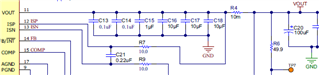
Please could you review my schematic? Confused what to do with EXTVCC and the feedback resistor calculation as the excel tool calculates it to be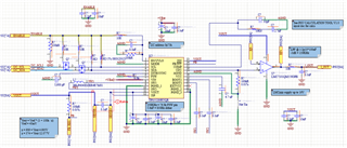 a different value
Tool/software:
Please could you review my schematic? Confused what to do with EXTVCC and the feedback resistor calculation as the excel tool calculates it to be a different value