This thread has been locked.

If you have a related question, please click the "Ask a related question" button in the top right corner. The newly created question will be automatically linked to this question.

TPS543C20A: TPS543C20A DESIGN

Part Number: TPS543C20A

Tool/software:

Hi Britton,

Couple of last questions before I release the design.

1. The output cap. configuration in the Excell calculator tool suggests a feed forward cap. for the 6 100uF ceramics I've included in the design, but not for 5 100uF ceramics on the output.

Should I remove a capacitor or insert a feed forward cap? Which one is the feedforward cap?

2. For inductor selection: I've chosen a 330nH inductor with DC resistance .165mOhms, Isat 65A and Irated 47.5A.  

My load current is ~26A and my KIND is .3 for this design.

I'm a little confused looking at an inductor current waveform which parts would be labeled iripple max/min, Ipeak... 
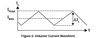
My understanding is I should be fine with an inductor with a rated current of 47.5A for a 26A load application. The temperature should only rise ~10K according to the datasheet for 26A
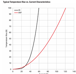
and the Inductor shouldn't saturate and begin to have inductance values change given its 67A sat current rated inductor.

When you get a chance could you provide me with a sanity check on the above information I provided?

Thank you,

Matt

  • Hi Matt, 

    I'll answer each below

    1. The feed forward capacitor is in parallel with the top resistor in the feedback resistor divider circuit between VOUT and RSP. As a best practice, I recommend to include a placeholder for both the feed forward capacitor and a 6th output capacitor, this is so you have flexibility if ever needed. That said, I would personally leave both of those unpopulated so that the BOM is built with 5x output capacitors and no feed forward cap. 

    2. Iripple max and Iripple min are the possible current ripples given the inductor tolerance. Ipeak is the expected largest possible current value (the peak of the inductor current ripple). In this case it is taking the maximum expected ripple 10A, dividing it in half, then adding that value to the 26A nominal current for an expected peak of 31A.

    Your inductor rating is sufficiently large

    Best regards,

    Britton