This thread has been locked.

If you have a related question, please click the "Ask a related question" button in the top right corner. The newly created question will be automatically linked to this question.

TPS61299: TPS61299 Circuit Validation

Part Number: TPS61299

Tool/software:

I am using a circuit based on the TPS61299ADRLR boost converter, as shown in the attached diagram.
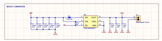
Circuit details:

  • Input battery: 2.8V (minimum) to 3.6V
  • Desired output voltage: 3.3V
  • Required output current: 0.4A

I would like to confirm if the circuit is correctly designed for these operating conditions. Is the configuration adequate to provide 3.3V with a 0.4A current from the specified battery? Are there any recommended adjustments or additional considerations to ensure the stability and efficiency of the circuit?

Thank you for your attention and support!

  • Hi Anoto,

    Thanks for reaching out. The circuit design looks fine, but I just want to ask why the input capacitance is so large. Also when Vin is higher than 3.3V, the device will actually go into pass through mode, which means the Vout will be equal to Vin, but with extremely high efficiency. Please take this into consideration.

  • Hi Zhong,

    Thank you for your response. The capacitors you mentioned were just for testing purposes. I appreciate your note regarding the pass-through mode, and I’ll take it into consideration for the project.