This thread has been locked.

If you have a related question, please click the "Ask a related question" button in the top right corner. The newly created question will be automatically linked to this question.

BQ40Z50-R1: bq40z50 with single cell application

Part Number: BQ40Z50-R1
Other Parts Discussed in Thread: BQ40Z50

Tool/software:

Hi,TI's Expert

  I've met a issue about using BQ40z50 with a single cell case.

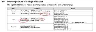
  There is the thing. I set the OTC Threshold as 45 degree, and the OTD as 60 degree.

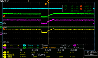
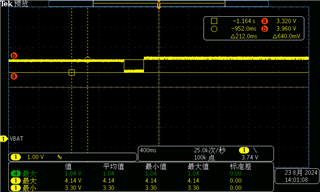
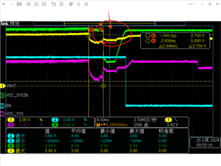
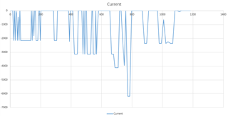
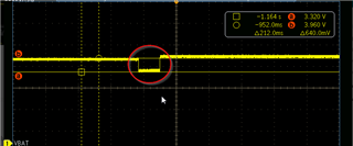
  When I test the battery discharge performance during the [45,60]degree, I found that the PACK voltage has a drop that make my mainboard work fail. PLZ refer the waveform in attachment. 

  Then, I think the gauge has a paradox whcih is, when the battery work over OTC and below OTD, means the chargeFET has cloesd and dischargeFET not yet. At that time, when load current increase, only when gauge detect the load current, gauge can open the CHGFET to discharge to the load. It need time to the whole process that would make a voltage drop at The PACK voltage when current though the CHGFET body diode, make my board work fail, further.

   Thanks.

  • Hello,

    I have a few questions.

    1- Are you using our Evaluation Board? If not, please share your schematic.

    2- Please share your settings - gg file

    3- Please share a log file. 

    When OTC happens, CHG FET is off. When OTD happens DSG FET is off. Regardless of OTC or OTD, the battery pack voltage should never drop. Unless there's something wrong in the schematic. 

  • There are .gg file and the log file in attachment.

    But, I still want to make myself clear that when cell at the certain temp like 55 degree when OTC set as 50 and OTD set as 60, which means the CHGFET is off and DSGFET still on. 

    So, when a rush load occurs, the gauge can open the CHGFET after a small load current has been detected. That process need time, during the time that CHGFET open, the current from cell can only though the CHGFET's body diode.

    If the issue can be solved, PLZ give me a spec of the mechanism

    4628.battery.gg.csvbattery.xlsx

  • Hello,

    I see an abnormal behavior in the log file. The gauge detects Charging State when the current is negative. When there's negative current, OTC should never occur. Charging means positive current. 


    Please share your schematic if not using TI's Evaluation Board.

    Having a 2A current load flowing through the body diode of the CHG FET can damage the FET. 

    The current test you are performing is not showing good behavior since the gauge should detect Discharge mode instead of Charge. But to answer your question. If CHG FET is off and DSG FET is ON and a load is applied, the gauge will let current flow through the body diode. Note that if current is greater than body diode threshold parameter, it will turn the FET back on to prevent FET from damaging. This body diode FET feature is controlled by FW and it can have a delay up to 2 seconds to react. 

  • Sorry that I can not share the schematic at this moment cause the BMS board is NOT product by us, But I'll get it and share it as soon as possible.

    As you mentioned, the gauge has a misbehavior during discharge,  which factors can cause this?

  • Likely SRP and SRN pins flipped. Hard to say without schematic. 

  • ok, I'll share the schematic to you as soon.