This thread has been locked.

If you have a related question, please click the "Ask a related question" button in the top right corner. The newly created question will be automatically linked to this question.

LM431: Making an over voltage and under voltage protection circuit using the LM431

Part Number: LM431
Other Parts Discussed in Thread: TPS3762, , TLA431, TL431

Tool/software:

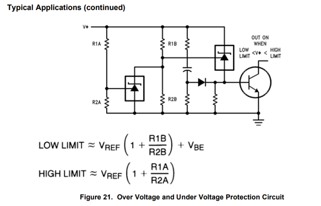
I am trying to build the following circuit but I am confused on how it works, and how the unlabeled passive components are sized. If I understand correctly, when V+ is between the low and high limit, the gate voltage will be almost 0 and the NPN will be an open circuit, but while while V+ is outside that range, the NPN will be turned on and have the connection grounded. So for the unlabeled parts, will any value work for the resistors, the capacitor, and the diode? Or is there a way to size them.

Thank you

Ryan

  • Hi Ryan,

    There are a few methods you could use for over voltage and under voltage protection, or what we also call "window" voltage protection:

    1. Using a voltage supervisor IC

    All of the window voltage monitoring functionality is integrated into one singular chip in this method. This can simplify design and provide higher accuracy. For example, TPS3762 can be connected directly to power rails up to 65V for continuous monitoring of overvoltage (OV) and under voltage (UV), also known as "window", conditions. This would remove much of the errors and potential mistakes that come from resistor and transistor sizing that may be necessary. You can choose an adjustable version of this part or a fixed version.

    What voltage levels are you trying to monitor?

    2. Using multiple shunt voltage references.

    This method can be done with multiple different circuit configurations. One example is the one you found in the LM431 datasheet. This method uses resistors to divide the voltage from the power rail to a value that would be 2.5V when the desired threshold is met. When this happens, LM431 starts to conduct current or stops conducting current depending on if you are implementing the over voltage or under voltage side of the window. 

    If you are willing to consider a very similar, but slightly different circuit configuration, this application note goes into detail on how to design this circuit:

    https://www.ti.com/lit/an/slva987a/slva987a.pdf 

    Section 6 on page 10 is probably what you are looking for, although the entire application note is helpful. Additionally, https://www.ti.com/lit/an/snvaa58/snvaa58.pdf describes well how shunt voltage references operate in this application, but does not show a window voltage protection example. LM431, TL431, or TLA431 would all be good devices to consider for this application.

    Thanks,

    Jackson