This thread has been locked.

If you have a related question, please click the "Ask a related question" button in the top right corner. The newly created question will be automatically linked to this question.

BQ25185: Help with general schematic design and the SYS connection

Part Number: BQ25185
Other Parts Discussed in Thread: TLV755P

Tool/software:

Hello everyone,

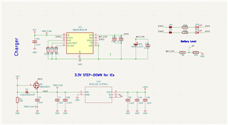
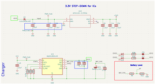
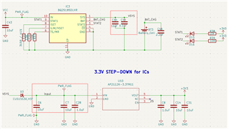
I'm replacing the battery charger model in order to have a more flexible version to also connect to solar panels to charge battery at 1000mA.

I have some doubts concerning the connection of SYS to the Q1 (DMG2307L). 

Additionally, I consider keeping the STAT1 and STAT2 disconnected by default avoiding the connection to a LED.

Are those solutions correct? The schematic, in general, looks correct (resistor and capacitor values, and connections) ?

  • Hello Saulo,

    Here are my comments on your schematic:

    1. If STAT1 or STAT2 are not being used, then they can be left floating because they are open drain outputs. A pullup resistor is only needed on these pins if you want to use the status signals, which can also be connected to IO pins of an MCU. Additionally, the cathodes of the LEDs should be connected to STAT1 and STAT2, while the anodes are pulled up.
    2. I see that you are using a voltage divider to measure the battery's voltage. Keep in mind that this will draw current from your battery.
    3. I don't see any issues with the configurations of TS/MR, ILIM/VSET, or ISET. I recommend that a ±1% tolerance or better resistor is used on ISET to minimize charge current error.
    4. I recommend connecting SYS of BQ25185 to VIN of the 3.3V linear regulator. Since BQ25185 has power path, the 3.3V linear regulator will receive power from the adapter when it is plugged in. When an adapter is not plugged in, then the 3.3V linear regulator will be powered by the battery through the internal BATFET. However, this all ultimately depends on the goals of your specific application.

    Please let me know if you have any further questions.

    Best regards,

    Alec Lehman

  • Hi Alec,

    Thanks for your feedback. I have changed a few parts of the schematic.

    1. Revised. The picture below shows an open jumper for each STAT, but I am considering removing them and leaving them connected.

    2. I'm aware of this. Considering to remove (or use an open jumper to help, during the test phase, how much it drains the battery).

    3. Noted.

    4. Revised. I connected the SYS to the VIN of the U10. Should I take a closer look at the values of the capacitors of the VIN or do they look okay to you?

    Best regards,

    Saulo

  • Hello Saulo,

    1. Revised. The picture below shows an open jumper for each STAT, but I am considering removing them and leaving them connected.

    I recommend pulling up the LEDs to the 3.3V output of the linear regulator instead of VSYS. This way, the LEDs will draw less current when they are on.

    2. I'm aware of this. Considering to remove (or use an open jumper to help, during the test phase, how much it drains the battery).

    If you're looking for a battery fuel gauge for your design, I recommend searching our portfolio of gauges.

    4. Revised. I connected the SYS to the VIN of the U10. Should I take a closer look at the values of the capacitors of the VIN or do they look okay to you?

    Please refer to section 9.2.2.3 "Recommended Passive Components" in the BQ25185 datasheet. For the BQ25185 in your schematic, the amount of capacitance that you have on VIN, SYS, and BAT is within our recommendations.

    For the 3.3V linear regulator, Texas Instruments has TLV755P, which is stable with 1uF capacitors on its input and output pins. Generally, the more capacitance there is on VSYS, the larger the inrush current to VSYS will be. I recommend checking the datasheet of the linear regulator that you are currently using to see how much capacitance is recommended on its input and output pins.

    Best regards,

    Alec Lehman

  • Thanks again, Alec

    1. Okay, that makes sense. Fixed that.

    2. I'm going to remove that and add a battery gauge when I extend the functionalities using a shield.

    3/4. We are using a 600mA linear regulator and the TLV755P has an output of 500 mA, so we will keep the current one and review the capacitors (inside the red box), considering your comments concerning the inrush current.

  • Hello Saulo,

    I'm happy to help. Feel free to reach out if you have any further questions or encounter any issues.

    Best regards,

    Alec Lehman