Because of the Thanksgiving holiday in the U.S., TI E2E™ design support forum responses may be delayed from November 25 through December 2. Thank you for your patience.

This thread has been locked.

If you have a related question, please click the "Ask a related question" button in the top right corner. The newly created question will be automatically linked to this question.

BQ25672: - Schematic review and battery cutoff questions

Part Number: BQ25672
Other Parts Discussed in Thread: TPS2121, BQ25620, TLV810E, TPS3899

Tool/software:

Hello

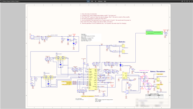
I have the schematic below. I had some questions related to it.  They are as follows:

1. Over all review of schematic
2. In default mode what voltage does battery cutoff?  Turn back on?
3. The "Ship FET" seems to raise the above voltage. Why?  We wish to match LiPoly cutoffs.
4. Are there advantages to adding the Ship FET?
5. Can the BQ25672 be fashioned into a "power switch" of sorts?  We would want the power to
return when the LiPoly voltage rose above VBAT_UVLOZ(?)
6.  Normal operation of unit is batteries only.  On occasion has solar input for charging
  • Hi Jeff,

    BAT UVLO specs are below.  There is a typo with rising, falling.  The higher values are rising.  The BATP pin powered charge pump for shipFET's SDRV needs a higher voltage to power up.  There are no user bits to turn on/off the shipFET.  The shipFET allows for ship or shutdown, which allow for the lowest BAT Iq's.

    Regards,

    Jeff

  • Hi Jeff

    Thank you but like to dig into this a bit further before we close the issue. 

    I wish to use a LiPoly battery and "out of the box" with default settings, I want the cutoffs to more closely match it.  That is, when the battery goes below a certain voltage, SYS is shut off, and when it goes above a certain volte, SYS is turned back on.   It seems on your data sheet, that those are 3.4 and 3.6 respectively with a shitFET installed. 

    So to do this, I SHOULD use a shipFET?

    Now the cutoff at 3.4 voits is fine, however the cut in voltage of 3.6v is a bit low (but I can work with it).   So optimally, I should reset that to a higher voltage via the I2C?

    We missed a few questions also

    Any comments on the overall schematic?

    Can the BQ25672 be fashioned into a "power switch" of sorts?  We would want the power to return when the LiPoly voltage rose above VBAT_UVLOZ(?)

    Thank for the quick turnaround


  • Hi Jeff,

    The UVLO settings are not adjustable.  If you are not concerned with battery drain while the end equipment is being shipped or stored, then you don't need the shipFET. 

    I didn't notice any obvious errors on the schematic.

    I didn't understand the power switch question.  When V(BATP)>UVLO rising, the shipFET auto turns on thereby restoring power to SYS.  There is no user bit to turn on SDRV and therefore shipFET on and off.

    Frankly for a 1S application, the shipFET is difficult to justify due to the high BAT_UVLO for turn on.

    Regards,

    Jeff

  • Lithium Ion batteries typically are completely discharged at ~3.0 volts. Therefore having a UVLO cutoff of 2.4 volts (no shipFET) isn't helpful.  With the shipFET installed, this rises to 3.2 volts, which is helpful.

    As to the turn on voltage, 3.6 volts is fine, being most Lipo's spend most of their life at 3.7 volts and when charging, can reach 4.2 volts

    Does that clarify my question a bit?

  • Hi Jeff,

    Yes.  You have probably figured out that this device isn't ideal for 1S operation.  We have other chargers better suited for 1S LiIon batteries but none with dual input MUX.  Also, the charger's BAT UVLO is not intended to replace the pack protector UVLO function.  You might find a better 2 chip solution using TPS2121 MUX IC plus BQ25620 3A 1S charger, for example.

    Regards,

    Jeff

  • Well, it would have been good to know that 9 months ago when we submitted it for a design review, plus the data sheet does spec it for 1S operation.

    In any case, we are were we are at this point. NOT trying to use the part as a pack protector, quite the opposite.  I don't want our battery pack's pack protector to kick in before the BAT UVLO. Hence the question about the shipFET.    So with it installed, our cutoff will be 3.4 volts?  We are regulating to 3.3volts in our application so we aren't losing much.  

    The device is solar powered.   We chose this part as it had a solar input that supported MPPT tracking.   How would the BQ25620 perform in this scenario?  These are 12-18volt solar cells,  10-15watts


  • Hi Jeff,

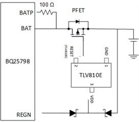
    To clarify, we have customers who use BQ25672 as a 1S charger but most do not use the shipFET due to the high BAT UVLO.  You could add a circuit similar to below to make your own shipFET feature:

    The TLV810E is an SVS (comparator and reference) with Iq=250nA and active-high push-pull output.  It turns on the PFET when charger REGN is up, indicating power is applied at VBUS, or if the 1S battery is above the SVS threshold (there are few to chose from).  TI has other slightly more expensive SVS's IC with lower Iq but not many with active high RESET (instead of /RESET) output.  For example the TPS3899 has Iq=25nA but only has active low output so you would have to add an NFET to invert the logic.

    Unfortunately, the BQ25620 does not have a MPPT feature but it has the VINDPM circuit upon which MPPT is based.  Host software could implement MPPT be periodically forcing the charger IC into HiZ (no switching) mode, reading the panel VOC with the charger's ADC, changing VINDPM to ~80% of the measured voltage and re-enabling the charger.

    Regards,

    Jeff