Because of the Thanksgiving holiday in the U.S., TI E2E™ design support forum responses may be delayed from November 25 through December 2. Thank you for your patience.

This thread has been locked.

If you have a related question, please click the "Ask a related question" button in the top right corner. The newly created question will be automatically linked to this question.

UCC28070A: ucc28070a

Part Number: UCC28070A

Tool/software:

Hello,

We are using this controller for a PFC with universal input 85 Vac till 265VAC.

The PFC is designed for 2250W nominal.


When we connect the converter to a voltage of 230VAC for exemple, and then we load to 2000w and we try to find the power limit by increasing the power demand, the first time the output voltage starts to decrease around 2240W.

When we remove the load (transient from 2000 W to 0 or  transient fromm 2000W to 500W ) and when we apply again the load ( 2000 W) , and when we try now to find the the power limit, the converter starts to reduce the output voltage around 1850W.

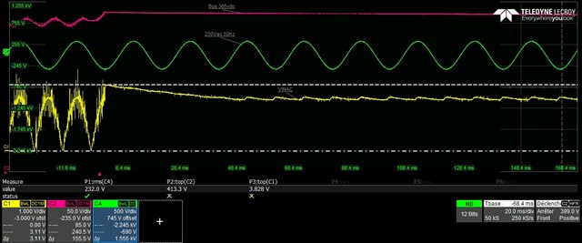
Here attached the measured voltage on Vinac in yellow  when we remove the load from 2000W to 0W
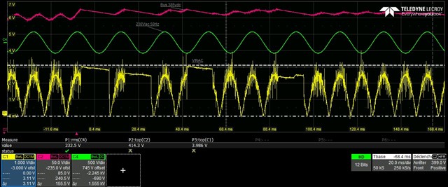
and when we change the load from 2000W to 500W
It seems that the controller has kept in memory the wrong KVFF value after removing the load.

We can obvserve some transients on vinac when we change the load, but the voltage has came back to its right value after few miliseconds.

Why the converter keep in memory, the wrong kvff value?

Do you have an explanation, or advices to solve this problem ?

Thanks  a lot , 

Gregory 

  • Hello Gregory, 

    When you suddenly remove the load from 2000W to 0W or to 500W, the low bandwidth of the voltage-loop cannot change the VAO voltage level immediately.  In fact, in your design it appears that your VAO decreases slowly over several AC line cycles before settling to the correct level for low load.

    At your un-load step, the output current immediately reduces, but the input current continues at the 2000W level because VAO has not yet decreased.
    With much lower load, but still 2kW input, your output voltage increases to the OVP threshold and switching stops. 
    Your bulk voltage falls very slowly with 0A load.  With 500W load, Vbulk falls to below OVP in about 12ms and switching resumes.

    VAO still has not settled to the new lower power level, so excess input power generates another OVP.  For the 500W load, OVP happens 4 times before the VAO level is low enough to regulate Vout (Vbus) at 500W.

    For a drastic un-load step, OVP is almost unavoidable.  But the number of OVPs can be reduced by increasing the bandwidth of VAO.  Examine your VAO compensation vlaues to ensure that your bandwidth is not excessively low (like 3hz or something like that).  8~10Hz cross-over frequency can react faster and still provide low THDi.

    For the VINAC signal, it senses the voltage after the diode bridge rectifier (or a separate rectifier).  With high load, there is high current in the EMI filter before the bridge. 
    On an un-load step, the high current trapped in differential-mode inductance continues to peak charge the voltage after the bridge until it is clamped by the output voltage.   

    Since the OVP has stopped switching, VINAC bleeds down slowly due to its own divider resistance. The peak charging may have set the VINAC level to the highest kVFF level, but the correct level will be reset by the peak of the VINAC signal following the next zero-crossing of VINAC. 
    VAO is changing so slowly that the VINAC peak levels hardly make any difference in the input power anyway. 

    I recommend to evaluate the VAO compensation and see if the cross-over frequency can be increased without significantly degrading THDi. 

    Regards,
    Ulrich 

  • Thanks a lot Ulrich