Tool/software:
Hello,
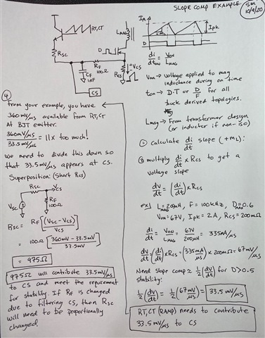
I am an electrical engineering student, and I am working on designing a push-pull converter using the LM25037. Throughout the design process, I am trying to understand everything, but I am having some difficulty with the practical implementation of slope compensation. The datasheet includes equation (6) for determining Rslope, but I am unsure how to express the equation. How can it be derived?
Is the equation based on determining the time dependency of the RAMP voltage? I have attempted this but ended up with a transcendental equation, which makes it difficult to express Rslope.
I would like to understand it thoroughly, as I also want to examine the effect of Cfilter on slope compensation. If I am correct, this has been neglected in the equation.
Thank you in advance for your help.


