This thread has been locked.

If you have a related question, please click the "Ask a related question" button in the top right corner. The newly created question will be automatically linked to this question.

LM5155EVM-SEPIC: Diode Anode Oscillations - Ringing

Part Number: LM5155EVM-SEPIC
Other Parts Discussed in Thread: LM5155,

Tool/software:

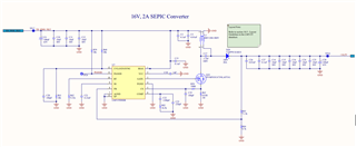
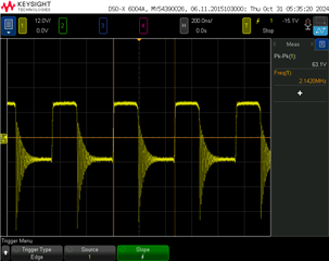
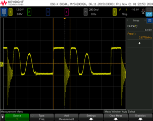
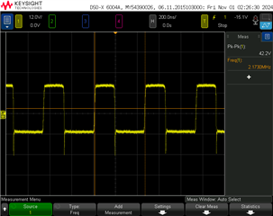
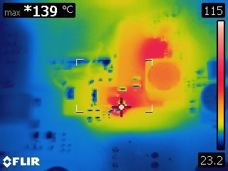
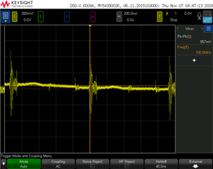
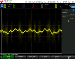
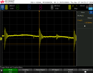
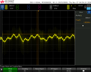
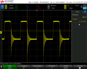
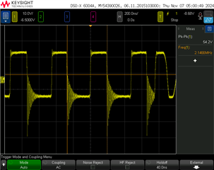
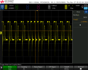
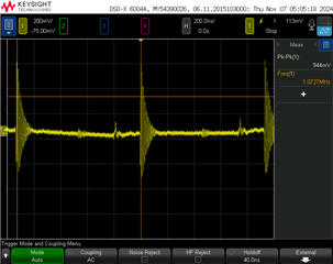
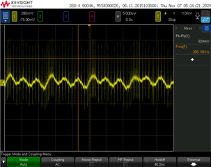
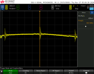
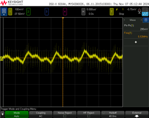
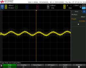
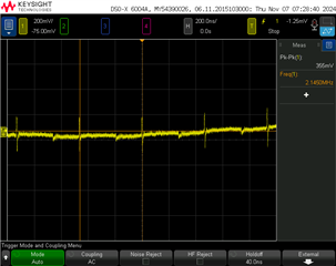
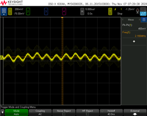
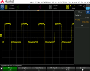
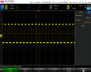
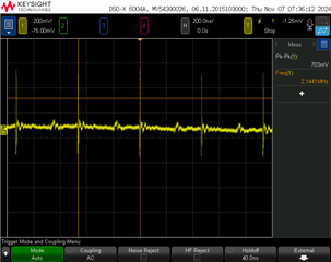
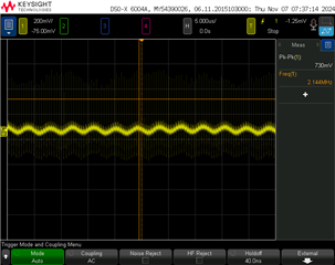
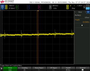
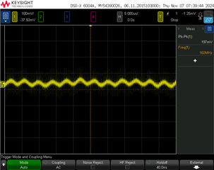
The same ringing issue mentioned in a previous post was observed in our LM5155 SEPIC design. We installed a snubber network in parallel with the output diode as described by the links provided in the post. This increased the input current draw to the system by 200mA and the snubber resistor and diode are getting hot. Is this a normal condition after suppressing the ringing? The previous post that described this problem, https://e2e.ti.com/support/power-management-group/power-management/f/power-management-forum/1006500/lm5155evm-sepic-the-evm-board-has-ringing, mentioned that there is reduced efficiency with the added snubber. 

Is this the expected performance of the SEPIC with the snubber installed or is there some other issue that needs to be addressed?

Thanks,

Jim

  • Hi Jim,

    Thanks for reaching out.
    Did you observe the ringing on the EVM or on your own design?

    If you saw it on your own design, please send me the schematic.
    Did you follow the instructions given here : https://www.ti.com/document-viewer/lit/html/SSZTBC7 ?

    Best regards

    Moritz

  • Hi Moritz,

    The original schematic (below) does not include the snubber network but the installed values on the PCB are 7.3 ohms ( 3 x 21 ohms in parallel ) in series with a 1nF capacitor in parallel with the D20 diode. I used the document that you referenced to calculate the snubber values which are 5.46 ohms and 752 pF. I didn't have the exact values so I used the values described above. The schematic is a Webench design for balance and follows the LM5155EVM layout very closely. 

    Best regards,

     Jim

  • Hi Jim,

    Thanks for the schematic.

    So the snubber you use reduces the ringing, but gets hot?

    Can you try to change the order of cap and resistor please?

    Also did you try to add a small gate resistor to slow down the FET?

    Best regards

    Moritz

  • Hi Moritz,

    I'll swap the cap and resistor order. The gate resistor has been discussed but not implemented. The revised schematic does have a gate resistor component pad added. I will try adding a small gate resistor.

    Best regards,

     Jim

  • Hi Moritz,

    I received some snubber parts and will attempt to install and test today with results to follow.

    The original E2E post by Arkady Ler that described this issue is titled "LM5155EVM-SEPIC: The EVM board has riinging." The response by Stefan Schauer (Jun 21, 2021) mentioned the following: So the main part of the oscillation in the Rectifier Anode has already been damped. Of course this needs to go on cost of the efficiency." 

    I am interested in knowing what temperature rise was observed on the circuit that Stefan worked on.

    Best regards,

    Jim

  • Hi Moritz,

    I was able to make some measurements with the gate resistor installed and then the snubber installed.

    The first image shows the waveform at the anode or the output diode as a baseline reference.

    The second image shows the anode waveform with the 5.1 ohm gate resistor installed.

    The third image shows the anode waveform with the gate resistor and the snubber network installed.

    The addition of the snubber network, 5.6ohm in series with a 750pF cap, installed in parallel with the output diode definitely suppresses the anode oscillations, however, the thermal image shows the severe heating of the snubber resistor.

    The product is to be used as an Intrinsically Safe (IS) device and the component surface temperature will not be allowed IS certification. It doesn't seem to matter if the snubber capacitor and the resistor positions are interchanged, the heating still persists. I still like the snubber response from a radiated emissions perspective but the resistor heating will not allow us to proceed. Have any of your tests or experiments shown similar heating problems?

    Best regards,

    Jim

  • Hi Jim,

    Due to public holiday in Germany, please expect a reply by Monday.

    Best Regards,

    Feng

  • Hi Jim,

    What component size does your snubber resistor have?

    I recommend using at least a 1206 size, if it still gets too hot, you can also parallel resistors.

    About the check from 2021, we do not have any temperature measurement data.

    Best regards

    Moritz

  • Hi Moritz,

    I installed a 1206 5.6ohm resistor. This resistor is the one shown in the thermal image and reached 139C. Paralleling the resistors will be the way to go if we continue along this path but heating remains a problem for us with IS requirements. Also, the lower the input voltage the more current into the SEPIC and the heating of the snubber resistor and the power components becomes worse. 

    Best regards,

    Jim

  • Hi Jim,

    The Energy of this high ringing has to be absorbed somehow. So wehen it is absorbed in the snubber, it will cause heat.

    So ii see 2 possibilities:

    1. Reduce the rootcause of the ringing, so improving the layout for example can help. So the energy to be absorbed would be smaller.

    2. Accept the amount of energy and size the snubber accordingly.

    What is strange is your second scopeshot from above. This seems not to be a stable operation. Is this all the same operating condition?

    Can you please send a scopeshot that is showing Vin, Vout, anode (like above) and switchnode?

    Best regards

    Moritz

  • Hi Moritz,

    The second scopeshot was the anode waveform with only the 5.1 ohm gate resistor installed and no snubber network installed so I'm not sure what the SEPIC showed instability. Adding the snubber network changed the anode waveform a lot by reducing the ringing which increase loop stability.

    One question comes to mind regarding the control loop component values from Webench and the LM5155_56_Excel_Quickstart_Calculator_for_SEPIC spreadsheet. For the same operating conditions the Webench and Excel component values are quite different. Which is correct or best to use?

    I'll try and get the scopeshots you requested as soon as I can.

    Best regards,

     Jim

  • Hi Jim,

    In general i recommend to trust the excel calculator.

    Also with the power stage designer you can calculate the COMP values very precise: https://www.ti.com/tool/POWERSTAGE-DESIGNER

    Best regards

    Moritz

  • Hi Moritz,

    Here is the current configuration of the SEPIC converter. We added an input filter and output filter using ferrites as we need to anticipate removing the snubber (due to heating) and attempt to filter conducted emissions before and after the SEPIC to minimize radiated emissions.

    Note: Components R32, C31, C4, C8, R30 are not populated in the input filter. Components R37, C28 are not populated in the output filter.


    The waveforms at the nodes you specified, Vin, D20 Anode, Switching Node, and Vout look the same without the gate resistor or snubber network installed. There is ringing at the D20 anode as expected.

    The operating conditions are Supply Voltage 12V @ 1.15A, Vin 10.85V (IR drop from PCB trace and cable connections), Vout 16.17V at approximately 2A.

    When I add the 5.1 ohm gate resistor the following waveforms are observed.

    Supply input before input filter


    Vin (after the input filter and input to SEPIC)


    D20 Anode

    Switching  Node


    Vout


    Load (after output filter)


    Adding the snubber network (5.6 ohm 1206 resistor and 750pF 0603 capacitor) along with the 5.1 ohm gate resistor. Also noted is the power supply current draw increases approximately 200mA with the addition of the snubber network.

    Supply input before input filter

    Vin (after the input filter and input to SEPIC)


    D20 Anode

    Switching  Node


    Vout


    Load (after output filter)


    If you need anything else let me know.

    Best regards,

    Jim

  • Hi Jim,

    Thanks for the scopeshots.

    Did you already recalculate the compensation network?

    Or do you have the possibility to measure a bode plot in the lab?

    It seems to be somehow unstable with only the gate resistor.

    What happens when you are running without Rgate and without snubber? Does it run stable?

    Then i would recommend to go on without gate resistor.

    Best regards

    Moritz

  • Hi Moritz,

    I haven't recalculated the compensation network but may do so, time permitting, as well as a Bode plot measurement.

    The SEPIC is stable without the gate resistor and snubber so that may be the way we will proceed with this design. The added heat with the snubber is a significant concern in this design so we are considering priorities accordingly.

    Best regards,

     Jim