This thread has been locked.

If you have a related question, please click the "Ask a related question" button in the top right corner. The newly created question will be automatically linked to this question.

LM5012-Q1: EMI Problem

Part Number: LM5012-Q1

Tool/software:

Hi to all,

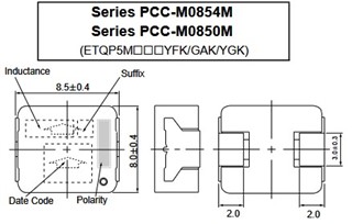
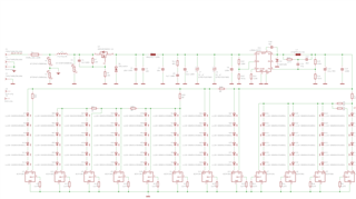
i finished my design with the LM5012-Q (Vin: 19.2V to 57.6V, Vout: 18V 12W). Circuit works fine after some capacitor improvement.

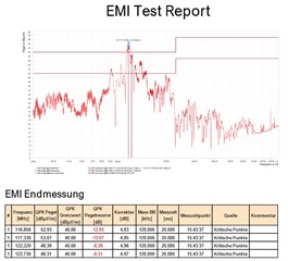
The issue now is, that EMC Test EN61000-6-3 E Field SAC 3m failed at 120MHz. (Switching frequency of my design is 200KHz).

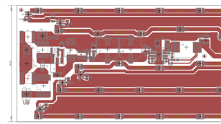
It failed at all input voltages (24V-48V-60V). Circuit is on a single layer aluminium board.

Testing engineer recommends a shielding case over IC, diode, choke.

Can you please have a look over my layout, if there are issues which create the EMC problem. Any ideas to avoid the shielding case?

Thank you!

Kind regards

Norbert

  • Hi Norbert,

    I looked into layout. I would like to point out that with switch mode power supplies it is very important to have a good layout. Make sure you follow the layout recommendations from the datasheet, and the EVM can also offer a good example as well.

    Particularly to minimize the effects of noise at the input due to discontinuous current loop, use a low value ceramic input filter capacitor to minimize the effects of the trace inductance. This capacitor should be located as close to the VIN pin of the IC. Keep lowest value capacitance closer to device VIN pin and then higher value.

    1. In this design i couldn't see that 10nF capacitor close to device. try adding couple of 2.2uF, 1uF,100nF capacitors at the input of the device.

    2. Use fully shielded inductor to confine the switching noises within inductor.

    3. The SW plane needs to be as small as possible only to handle required current. If the SW area is more, chances of radiated emission is high.

    4. Make sure that inductor orientation is correct. Try changing the inductor orientation and measure the result.

    Hope this helps..

    Thanks,

    Nitya

  • Hi Nitya, thank you for your hints.

    As mentioned in datasheet and EVM-Board, i populated a 100n (C9) directly at the IC-Input. I don't see a 10n in datasheet and EVM?

    Can you explain the need of correct inductor orientation? I'm using ETQP5M101YGK, which is a Panasonic metal composite core. On the choke ist marked "polarity". Must polarity go to the IC-side or to the output side?

    Regards

    Norbert

  • Hi Nobert,

    Polarity marked should be connected to high dv/dt side. That means it should go to IC side.

    Thanks,

    Nitya