This thread has been locked.

If you have a related question, please click the "Ask a related question" button in the top right corner. The newly created question will be automatically linked to this question.

BQ28Z620: Using BQ28Z620 Fuel Gauge CHG/DSG pins to drive BQ51051B CHG pin to stop charging when temperature threshold exceeds

Part Number: BQ28Z620
Other Parts Discussed in Thread: BQ51051B, , EV2400, BQSTUDIO

Tool/software:

Hi TI team,

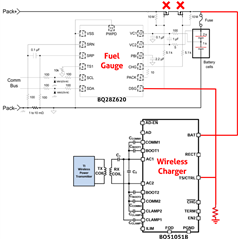
we are using the BQ51051B wireless charger IC on a design where we were measuring the temperature in a custom way to only allow charging on a temperature interval. Now, we would like to substitute this custom circuitry for a BQ28Z640 fuel gauge to control temperature but also getting some SoC and SoH parameters. 

We have been reviewing the recommended fuel gauge schematics, and all of them points to use a back to back MOSFET configuration to unplug the power line in case any alarm is triggered, by driving CHG and DSG pins. We would like to avoid the use of these two extra components and to connect any of these CHG and DSG directly to the CHG pin of the BQ51051B battery charger so that the charghing is stopped.

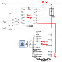
Another option could be to use the wireless charger AD pin to drive the charging operation. During the docs review, we ar only clear that, wireless charger CHG should be pull-down driven but not many information regarding the fuel gauge CHG/DSG internal schematic, so we do not know if these configuration proposed on the image could be possible.

Any information you could provided, will be welcome.

Regards,

eesy innovation.

  • Hello,

    The CHG and DSG pins are output pins and the CHG pin on the BQ51051 is also an output pin so that simple will not work.

    I wouldn't recommend this design choice since the CHG and DSG FETs are there also for other protections for the battery.

    Regards,

    Adrian

  • Hi, 

    you are totally right, the schematic is wrong. We meant to connect it to the TS/CTRL pin, which is for sure an input. This would be the right schematic, sorry for the inconvenient:


    Best Regards,

    eesy innovation

  • Hello,

    I this will not work either, Max voltage that can be applied to the TS/CTRL pin to head a logic high is 5V and the DSG/CHG pin from the gauge will output a voltage greater than this. This could damage the pin. If you don't want to use the DSG and CHG FETs then you need to keep those pins floating and use another mean of determining when to cut off current through the battery (can read out the voltage from the gauge and use logic on a host MCU is one idea).

    Regards,

    Adrian

  • Hi,

    thanks for your time. This was a suspicion, yes. We were wondering to use either TS/CTRL or EN2 pin of the wireless charger but using a MOSFET to conmute with DSG/CHG pins. We do not want to relay on a MCU the charging control, but make the power stage independent to avoid failures. Any idea you can provide would be good for us.

    Regards,

    eesy Innovation

  • Hello Fernando,

    Regarding your questions about the pins on the charger, I would recommend posting a new thread for the charger team to see. They are much more familiar with the functionality of the charger pins than I am.

    Regards,

    Adrian

  • Hi Adrian,

    fine, let's make it this way better, thanks!

    Regards

    Fernando.

  • Hi again Adrian,

    two more question regarding the Fuel Gauge, we have just acquired a BQ28Z620EVM to do some testing before including it in our design. We connected 2 4.2V Cells to the 2P, 1P and 1N connectors and tried several loads in Pack+, Pack-, as explained in the datasheet. However, we are not able to see any output voltage on the Pack pins. CHG is at ~4.2V, but DSG is 0V. We pulse the S1 button but apparently the Fuel Gauge does not start.

    What is the default configuration of the Fuel Gauge so that we can be sure it works quickly?

    Do we explicitly need EV2400 to configure the BQ28Z620? Is it possible to do it by I2C as detailed in the reference manual of the IC?

    Regards,

    Fernando.

  • Hello Fernando,

    Yes, you will need the EV2400 to program the ChemID onto the gauge, but other configurations can be done with a MCU. By default, the FETs are off on the gauge. You will need to turn them on. You can press the wake button on the EVM, this should cause an output voltage on Pack

    Regards,

    Adrian

  • Hi Adrian,

    Thanks! We press S1 and see the output changes while pressed with a multimeter, but the IC does not start and, when releasing the button, the output is bach to 0V, CHG to 4.2V and DSG to 0V. Any idea? Is there anything else we are missing?

    Regards,

    Fernando.

  • Hello Fernando,

    I see, then you will have to send the command to turn on the FETs on the gauge. You can use a host MCU to do this, or the EV2400 and BQStudio.

    Regards,

    Adrian

  • Hi Adrian,

    last day we were trying to send some commands using a MCU with the I2C pins. The schema we follow is as this. Would it be correct? The suspect is the fuel gauge is not started and hence not receiving anything.


    We couldn't get any communication. We are attempting to send this commands:


    If there is any quick guide or thread about using I2C to this in short steps, would be appreciated, thanks!


    Regards,

    Fernando.

  • Hello Fernando,

    I would recommend reading this document: https://www.ti.com/lit/an/slua801/slua801.pdf

    Regards,

    Adrian