This thread has been locked.
If you have a related question, please click the "Ask a related question" button in the top right corner. The newly created question will be automatically linked to this question.
Tool/software:
Dears,
The customer used LM5013 in the project. He encountered several problems:
1. The voltage designed by the customer is 3.3V, but the generated voltage is 3.5V
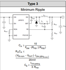
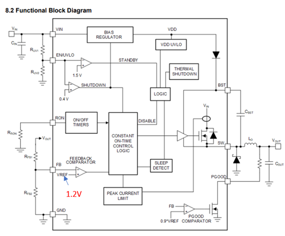
2. The voltage on R1465 is about 1.42V, not 1.2V as stated in the manual
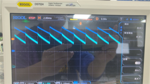
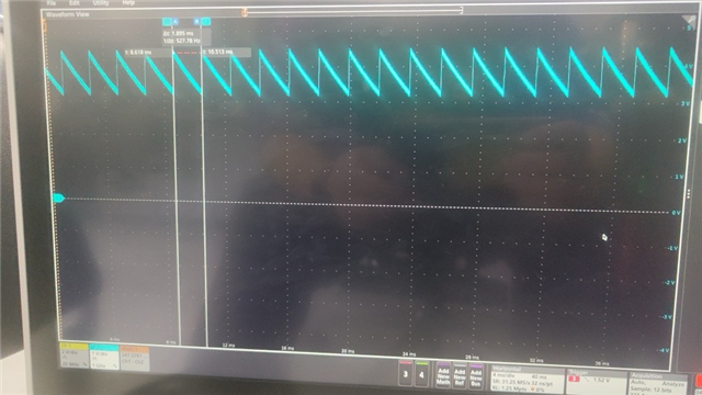
3. As shown in the figure, the output waveform of the voltage has huge ripples and the frequency is wrong
Please help analyze the reasons, the schematic diagram is as follows:
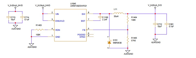
Many thanks!
Hi Arabella,
The above schematic does not have any ripple generation circuit. You need to have ripple generation circuits to operate the LM5013 device for low ESR output capacitors as shown below.
Refer page no. 12 of LM5013 datasheet for more details.
Thanks,
Nitya
The upper one is the output voltage, and the lower one is the FB pin voltage. The FB manual says it should be fixed at 1.2V. Why is the voltage ripple so large now?
Hi Arabella,
If the output voltage varies, the FB voltage also varies. It is just a resistor divider connection in between OUT and FB.
Thanks,
Nitya
Please make necessary changes that are mentioned LM5013 datasheet. The issue will be resolved.
Hi Arabella,
The VREF regulation voltage is 1.2V as shown below. The FB voltage is scaled down version of the output voltage and it is not fixed value. And the feedback voltage is compared with the Vref(1.2V) and depending on this error between VREF and VFB, the duty cycle is adjusted on the DC-DC converter.
For COT mode of controller to work reliably, you need to have voltage ripple at the feedback node. In schematic that is shared by you, does not have any ripple generation circuit and hence you are seeing the higher output voltage ripple.
There are many app notes from TI which explains the COT mode of operation.
1. https://www.ti.com/lit/pdf/SNVA776
Thanks,
Nitya