This thread has been locked.

If you have a related question, please click the "Ask a related question" button in the top right corner. The newly created question will be automatically linked to this question.

BQ79616: BQ79616

Part Number: BQ79616
Other Parts Discussed in Thread: USB2ANY

Tool/software:

Dear TI Support Team,

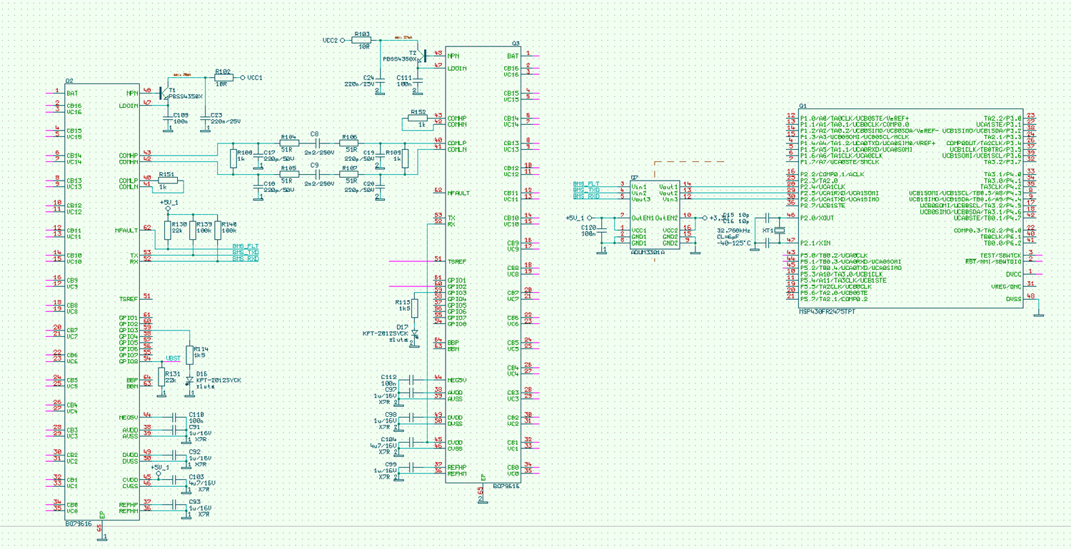
We're going to use your BQ79616 chips. On the board we have MCU MSP430FR... + two BQ79616. It communicates via UART to the first BQ79616, from it goes COMHx signal to COMLx of the second BQ79616 (Daisy Chain Communikations). We measure 30 cells. The UART is decoupled and the COMHx-COMLx is decoupled by a capacitor according to DataSheets.

Communication with the first BQ79616 works (after reset it has address 1).

After the auto-addressing sequence, the first component starts communicating with address 0. If I perform communication with the second BQ796816 chip at address 1, I miss the responses on the UART.
However, I can see on the oscilloscope that the second BQ79616 receives the request and responds with the initial byte count (I tried to read the voltage of the 16 cells and the COMHx-COMLx communication showed a 38 byte response).
But the data was no longer getting to the uart. The response signal has +- 3,8V. The error registers from the master BQ79616 are zero.

The fillet is the query to the second BQ79616, the yellow is the communication on COMH/L between the two BQ79616.

The query and response have different amplitude, but everything is normal.
Do they have to be acknowledged or triggered somehow to receive data, or should they come automatically?
Thank you very much for the answer.

  • Hi Ladislav Dreisig

    What specific read commands you sent?
    This looks like reading a read command for read seven registers.
    Can you measure UART or daisy chain with a logic analyzer?

    Regards,
    Wink

  • Hi Wink, thank you for your reply.

    I am sending the following commands as per the example:
    D0 03 4C 00 FC 24


    D7 03 43 00 00 00 00 00 00 00 00 00 00 61 6F // I tried without this synchronization


    D0 03 09 01 0F 74


    D0 03 06 00 CB 44


    D0 03 06 01 0A 84


    D0 03 08 02 4E E5


    90 00 03 08 00 13 DD


    90 01 03 08 03 52 20


    C0 03 4C 00 F8 E4

    Further reading attempts:
    - Device 0 query
    80 00 05 30 02 A0 1E // error reading + response

    - query on Device 1
    80 01 05 30 06 A0 21

    waveform detail on the link between device 0 and device 1

    Device 0 to Device 1

    Device 1 to Device 0

    Device 1 to Device 0 diferencial

    thank you for your reply and your time.

    Lada

  • Hello Lada,

    Let me look into these, I will reply by tomorrow. Sorry for the wait!

    Best Regards,

    Luis Hernandez Salomon

  • Hello Luis,

    I remind myself with my question. I need help with this.
    All attempts have the same result. The second component communicates with the first, but the first one does not send me data.

    Best Regards

    Ladislav Dreisig

  • Hello Ladislav,

    Apologies for the wait. I was unfortunately out of office until yesterday.

    You mention that you were not sync'ing, what is your auto-address sequence? Do you have a log of the sequences performed? A logic analyzer capture of the UART lines would be useful. 

    I saw that you also mentioned you used capacitive isolation, was this on the same PCB, or different boards? 

    Best Regards,

    Luis Hernandez Salomon

  • Hello Luis,
    I tried it with and without synchronization. Unfortunately, I do not have a logic analyzer that would translate the communication between two BQ79616 components. There is no classic UART there.

    Other communications can be seen in the previously sent pictures. From them, communication between components is also visible, The components have capacitive coupling and are on one PCB. They are 5cm apart.

    I am attaching images with communication between two BQ79616. My sent question: 80 01 05 30 06 A0 21 (from address 0x0530 read 7Byte)

    yellow signal - query from MSP to BQ79616
    blue signal - response from BQ79616 to MSP
    red signal - mathematically subtracted two differential signals of communication between BQ79616 and BQ79616

    The number of bytes in the response corresponds to 7 byte data and 6 byte header (If there is a similar communication there as on the uart.)

    The number of bytes in the response corresponds to 7 byte data and 6 byte header

    Measured voltage question

    Measured voltage answer

    Evidently, communication is taking place. If I ask the first component in the sequence about the same thing, they will answer me.

    Thank you.

    Láďa

  • Hello Lada,

    I am not sure why it is not working.

    Mind sending me your schematic? You can send it through Private Messages if you'd prefer. 

    Can you measure the timings of the daisy chain waveforms, and compare to what is shown in the following application note:

    This shows the timings required for communications to be successful. 

    Have you attempted doing these communications with EVM's? It may be good to test these with EVM's to ensure that it works on a known good board, so we can rule out if it is due to hardware of software.

    Best Regards,

    Luis Hernandez Salomon

  • Hello Luis,

    Sorry for the delay, but I have more projects. i got around to connecting the second piece of HW and the result is the same.

    here is the schematic:

    Have you tried any command sequence?

    Thank you.

    Láďa

  • Hello Lada,

    No worries! I will check the schematic by tomorrow.

    Command sequences should work fine with your device, I have used it many times in the past with no problem.

    Best Regards,

    Luis Hernandez Salomon

  • Hello Luis,

    So I checked the communication. On the second BQ79616 I have a diode on GPIO3 and I turned it on. So the data is passing through. But the response still doesn't get through the first BQ79616 to the processor.

    Don't I have to make a command to switch from setup to normal operation?

    Thank you.

    Láďa

  • Hello Lada,

    The daisy chain circuit looks okay to me.

    My only guess here is that the devices may have not been properly auto addressed. Do you have a log of exactly what sequence is being sent for the auto address sequence here?

    Best Regards,

    Luis Hernandez Salomon

  • Hello Luis,

    sequence is this:

    1) SYNC from D0 03 43 00 F9 D4 to D0 03 4A 00 FF 84
    2) D0 03 09 01 0F 74
    3) D0 03 06 00 CB 44
    4) D0 03 06 01 0A 84
    5) D0 03 08 02 4E E5
    6) 90 00 03 08 00 13 DD
    7) 90 01 03 08 03 52 20
    8) SYNC from C0 03 43 00 FD 14 to  C0 03 4A 00 FB 44
    9) 90 01 00 0F 04 E1 D2 - successful lighting of the LED on the second BQ79616
    10) 91 00 03 31 FF FF 4C A1 - null FAULT_RST1 and FAULT_RST2
    11) 80 00 05 2D 01 E9 4F - read FAULT_SUMMARY first BQ79616 (response 01 00 05 2D 00 00 91 0F)
    12) 80 00 05 52 02 89 7E - read FAULT_PWR1  first BQ79616 (response 02 00 05 52 00 00 00 E4 78)
    13) 80 01 05 52 02 88 82 - read FAULT_PWR1  second BQ79616 (see picture)


    Thank you.

    Láďa

  • Hello Lada,

    When you do broadcast reads, are you able to properly read the device? Is there any response there?

    Do you have an EVM? Or are you able to use our GUI using an USB2ANY? Wondering if sending the command sequence through it may help.

    The command sequence you shared looks okay to me in terms of the commands being sent. Did you confirm that the CRC was properly generated for each step?

    Very odd that there is no response returned. Apologies about the difficulties here. 

    By the way, have you tried replacing the IC's to see if it is possibly a faulty IC?

    Best Regards,

    Luis Hernandez Salomon

  • Hello Luis,

    The response is if I query only the first BQ79616.
    The second one just executes commands and sends responses to the first one.
    We have two boards made and both behave the same.
    The CRC calculation function works correctly, I checked the results with sample examples and the first BQ79616 works normally, except for forwarding responses from the second BQ79616.
    I will try to somehow connect your interface to our board.
    Unfortunately, I'm probably doing something non-standard, but it's strange that the first BQ79616 processes my query, sends it to the second BQ79616, processes it as well, replies and the last step doesn't happen.

    Best Regards

    Láďa

  • Hello Luis,

    I would like the BQAutoEval program to be able to connect via a universal USB to RS232 converter. Is there a way to set this up?

    Thank You.

    Láďa

  • Hello Lada,

    The engineer is currently Out of Office for today and tomorrow. They will be back Monday to provide a response.

    Thank you for your patience.

    Best Regards,
    Alexis

  • Hello,

    I ordered USB2ANY. After turning it on, the BQAutoEval software finds the USB2ANY converter, but my HW does not. I looked at the TX signal from the USB2ANY converter and there is no signal at all. When trying to communicate, nothing moves on it. It is at logical 0.
    Is there something to set or update the FW somewhere?

    Thank You.

    Best Regards,
    Láďa

  • Hello Luis
    I managed to upgrade usb2any to version 3.1.1.14 and everything started working. So I will listen to the settings and communication between QBEval and check the data that I send.


    Thank you for your cooperation.


    Best regards
    Ladislav Dreisig

  • Hello Luis,
    so I am now communicating with my HW.
    The whole problem was that after starting I sent wake-up and addressing + settings. The components responded, but the first BQ did not send anything from the second BQ. Thanks to your SW I found out the following thing. If I do not receive a response from the second BQ79616, I will send Power-Down (D0 03 09 08 CF 72) and start wake-up + initialization again, everything will start working.
    Have a nice day and thank you for your help.

    Láďa