Because of the Thanksgiving holiday in the U.S., TI E2E™ design support forum responses may be delayed from November 25 through December 2. Thank you for your patience.

LM5050-1: Issue with LM5050-1 O-Ring Circuit for Battery Chargers

Part Number: LM5050-1
Other Parts Discussed in Thread: LM5050-2

Tool/software:

Hi,

I am using the LM5050-1 to design a circuit that prevents current flow between two battery chargers when they are connected. I implemented an O-ring circuit with two LM5050-1 devices, but the ideal diode function does not seem to work as expected.

  1. When a battery (40–60V) is applied to the cathode, 8.7V is measured at the anode.
  2. When two chargers are connected, current flows between them. (In a circuit using the LM74700, both chargers detect the error and stop the current flow. This circuit worked well, but due to the low voltage rating, I wanted to use the LM5050-1.)

After repeating the above experiments, a spark occurred in the LM5050-1 on one channel. The device was damaged, and in another channel, the Gate and Source of the FET were shorted.

I will share the circuit diagram with you.

Thank you for your support.
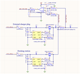
  • Hi Uiuk,

    When VOUT is powered, VS is also powered up and forms a path internally. Please go through the thread mentioned.

    (+) [FAQ] LM5050-1: LM5050-1 Leakage Current - Power management forum - Power management - TI E2E support forums

    Regards,

    Shiven Dhir

  • Thank you for your response.

    Even after following the suggestion to avoid the leakage path by connecting the VS pin to IN, or using the LM5050-2 (which takes the supply bias voltage through the IN pin and does not have a separate VS pin), the same issue persists.

    What I don’t understand is that the voltage seems too high for the claimed leakage current of 200 µA. If the ideal diode is functioning correctly, is it possible for 8.7V to appear at the anode when there is more than 20V(20~60V) at the cathode?

    It seems that reverse blocking is not working properly, even before addressing the issue of current flowing between the two chargers in the O-ring configuration.

    Could you provide further clarification?

    Thank you.

  • Hi Uiuk,

    Do you have LM5050-2 devices? Did you try testing the same condition with the other device already?

    You can try probing the GATE voltage and check if the MOSFET is turned-on. Ideally it should not be. If the GATE is low, reverse current blocking is working fine.

    Regards,

    Shiven Dhir

  • Hi Shiven Dhir,

    Thank you for your response.

    I noticed that the gate voltage does not drop to 0V. Instead, the gate voltage is also at 8V, which matches the anode voltage.

    I have already ordered the LM5050-2, but it does not seem to work correctly in its basic operation. Could you please investigate further to ensure that there are no other issues?

    Thank you for your assistance.

    Regards,
    Uiuk

  • Hi Uiuk,

    Since the VGS is 0V, the FET is in off state. Please disconnect the VS path by removing the 100ohms resistor to confirm that the voltage build-up is through VS only.

    Regards,

    Shiven Dhir