This thread has been locked.

If you have a related question, please click the "Ask a related question" button in the top right corner. The newly created question will be automatically linked to this question.

BQ2026: Cannot write all 16 bytes of data

Part Number: BQ2026

Tool/software:

Hi all

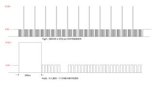
  When I use the circuit provided by EVM of BQ2026 to write data to EPROM, sometimes I can't write all bytes of data completely, sometimes I can only write 8 bytes. The waveform of SDQ pin of BQ2026  measured is shown in the attachment. 01 is the whole waveform, and 02 is the detailed waveform from one 12V pulse to the next pulse. Please assist and support. Thank you!

1.  Is the 12V Pulse to be maintatined? Or is the 12V pulse turned off as long as a 480us pulse is provided? I am currently using this scheme.

2. After all the data is sent to the cache, is it enough to output only one 480us pulse, instead of multiple 12V pulses like my current one.

  • Chime Xia,

    To answer your questions:

    1. The 12V pulse should be issued for each byte (Figure 8 on Page 9 of the datasheet). Each byte is written to the onboard cache, then SDQ is pulled up to 12V for at least 480us. This should be a single pulse.

    2. The cache can only hold 1 byte at a time. You should issue a 12V PROG pulse after writing each new byte to the cache. It's recommended to validate each byte written to the cache before sending the 12V PROG pulse. (Section 7.3.1 in the datasheet)

    In order to better solve your issue, can you tell me more details about your setup:

    • Are you using the CRC check to verify the byte was written to the buffer correctly before sending the 12V PROG pulse?
    • Are you driving the PROG pin with a GPIO pin from the MCU?
    • What pull-up resistance have you selected for the SDQ line?
    • Can you attach an oscilloscope screenshot of the write process, with the probe connected to J3 on the BQ2026EVM?

  • Thank you for your reply!

    the answers to your questions are as follows:

    1.It's one pulse per byte.

    2.that drive signal is sent to the GPIO pin through the MCU.

    3. the BQ2026 is  provided with a 5.1k pull-up resistor.

    4.Because the MCU is damaged during debugging, and now I want to rewrite the corresponding code, there is no debugging screenshot provided.

     Thanks

    Xia chime

  • Xia Chime,

    Points 1 thru 3 look good. For 4, if you run into any issues, let me know!

    Shane