Other Parts Discussed in Thread: BQ25798, BQSTUDIO, , BQ40Z50
Tool/software:
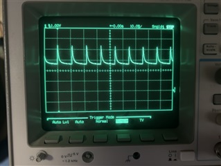
Hi there—we received a customer return with the note that the product cannot charge. I reproduced the issue, and found that our charger (BQ25798) elicits continuous VBAT OVP faults; this is confirmed by the following capture of VPACK:
This is typically a sign that neither the CHG FET nor the PCHG FET are closed, so I connected BQStudio to query the state of the gauge during the failure mode. There was no charging fault (XCHG = 0), and the only safety status (SS) fault was undervoltage (CUV = 1) which is expected:

The register map shows the gauge operates in precharge mode (PCHG = 1), which is expected given the pack voltage was roughly 2.3 V, and our precharge threshold is 2.5 V. When I probed the PCHG pin of the gauge, however, it was only 50–100 mV; this is far too low to enable the PCHG FET:

I then sent the FETControl command (0x0022) to disable FW control of the FETs, followed by PrechargeFETToggle (0x001E) to forcibly enable the PCHG FET. The manufacturing status register changed from 0x0018 (FET_EN = GAUGE_EN = 1) to 0x0009 (FET_EN = 0, GAUGE_EN = PCHG_TEST = 1), but the PCHG pin of the gauge remained 50–100 mV as above.
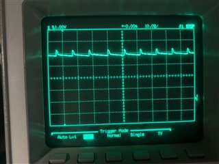
I then sent PrechargeFETToggle (0x001E) once more to forcibly disable the PCHG FET. The manufacturing register changed to 0x0008 (FET_EN = PCHG_TEST = 0, GAUGE_EN = 1), and the PCHG pin of the gauge was pulled up as follows:
My naive assumption is that there is some sort of HW problem here—is there any other explanation for why the gauge cannot drive the gate of the PCHG FET?
The schematic of our pack is identical to figure 9-1 of the BQ40Z50-R2 datasheet, modified according to the datasheet for a 1S design. Our golden file is linked here: 6683.gg.csv
In case I can provide any additional information, please let me know. Thank you in advance!